Component replaCement
6-16 powermax
45
Service Manual
Replace the control board
1. Turn OFF the power, disconnect the power cord, and disconnect the gas supply.
2. Use a #2 Phillips screwdriver to remove the 2 screws from the handle on the top of the power supply. Tip the end
panels back slightly so that you can get the edges of the handle out from underneath them. Lift the cover off the
power supply. Remove the Mylar barrier that protects the power board.
3. Remove the amperage control knob by pulling it straight out from the end panel.
4. Remove the front end panel, or gently tilt it away from the base.
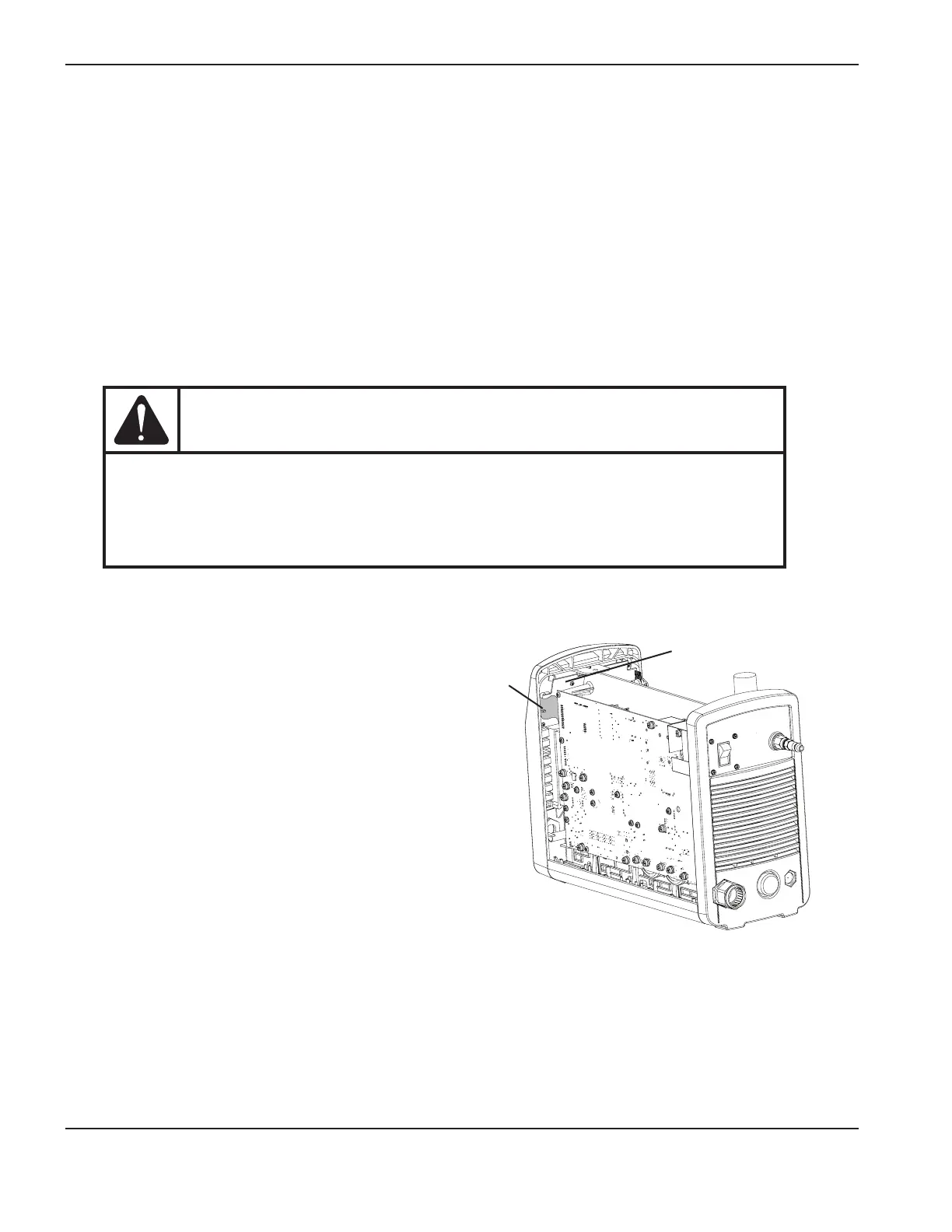
5. Detach the ribbon cable from the power board at J7 (200–240V CSA and 230V CE) or J8 (400V CE and 480V
CSA).
CAUTION
Static electricity can damage circuit boards. Use proper precautions when handling
printed circuit boards.
– Store PC boards in anti-static containers.
– Wear a grounded wrist strap when handling PC boards.
6. Test the new control board before installing it by attaching its ribbon cable to the power board. Reconnect the
power, turn the system on, and verify that the start LED on the control board is the only LED illuminated. Also, the
fault LEDs on the front panel should be extinguished.
7. Disconnect the electrical power and the ribbon cable
again, and set aside the new control board.
8. Remove the 3retaining screws from the old control
board and lift it out of the power supply.
9. Screw the new control board into place with the 3
retaining screws and then attach the ribbon cable.
10. Press the amperage control knob onto the post. There
is a flat side on the post. Ensure that the flat side of
the opening in the knob aligns with the flat side on the
post.
11. Reposition the front end panel.
12. Being careful not to pinch any of the wires, replace the Mylar barrier and slide the cover back onto the power
supply. Position the handle over the holes in the top of the cover, then use the 2screws to secure the cover.
13. Reconnect the electrical power and the gas supply.
Control board
Ribbon
cable