TroubleshooTing and sysTem TesTs
powermax
45
Service Manual 5-19
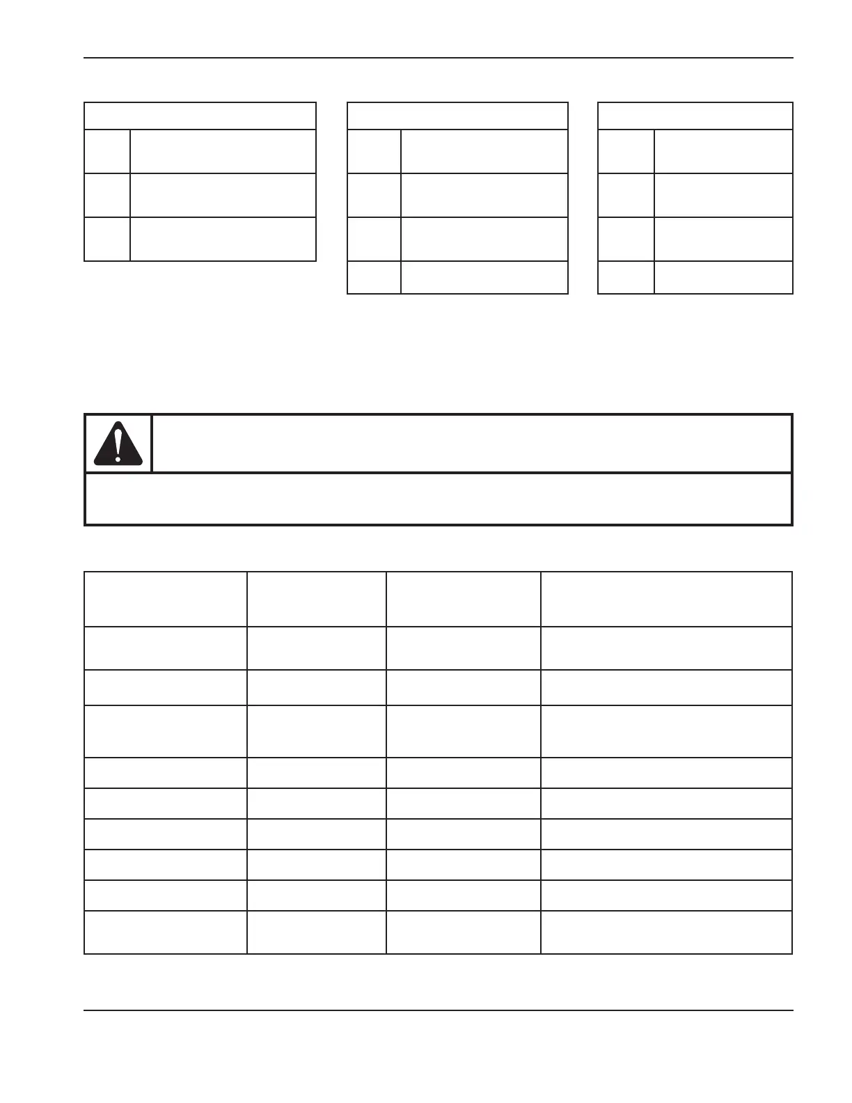
Single phase Three phase (CE) Three phase (CSA)
L
Black (CSA)
Brown (CE)
L1 Brown L1 Black
N
White (CSA)
Blue (CE)
L2 Black L2 White
PE
Green (CSA)
Green/yellow (CE)
L3 Gray L3 Red
PE Green/yellow PE Green
Test 2 – power board voltage checks
With the power ON, use a meter to verify the voltages at the J7 pins (J8 on 400V CE and 480V CSA power supplies)
listed in the following table to be certain that the power board is functioning correctly. If any of the values are incorrect,
replace the power board.
CAUTION
Do not use -VBUS as ground – doing so could destroy the power supply. Instead ground to either the
ground wire clip on the rear panel or to the heat sink as shown below.
Note: All values can be ±10%.
J7 or J8 pin number to
ground
Test
Expected value
(200–240V CSA or
230V CE)
Expected value
(400V CE or 480V CSA)
19
VACR (rectified AC
line voltage)
1.95V at 230 line
voltage
2.7V at 400 line voltage (CE)
2.016VDC at 480 line voltage (CSA)
21
VBUS (DC bus
voltage)
2.28VDC at 385VBUS
2.178VDC at 560VBUS (CE)
2.016VDC at 670VBUS (CSA)
18
(200–240 and 230V
only)
IPFC (input current) < 0.1VDC Not applicable
20 IFB (output current) < 0.1VDC < 0.1VDC
22 ITF (transfer current) < 0.1VDC < 0.1VDC
25 3.3VDC 3.3VDC ±5% 3.3VDC ±5%
24 5VDC 5VDC ±5% 5VDC ±5%
12 24V sense pin 2.2VDC 2.2VDC
16 Start signal
3.2VDC closed
0VDC open
3.2VDC closed
0VDC open