B W
MILLER EDGE
GEM
CONNECT TO GATE EDGE
WITH 10K OHM RESISTOR
24V AC Accessory power
+ 24
V
D
C
COMMON
STOP BUTTON
OPEN BUTTON
CLOSE BUTTON
REMOTE OPEN AND
RADIO CONTROL
OPEN/CLOSE
1
OPEN PARTIAL
INTERLOCK OPEN
TIME CLOCK OPEN
FREE EXIT DETECTOR
DISABLE EXIT DETECTOR
DISABLE CLOSE TIMER
INSIDE OBSTRUCTION
VEHICLE DETECTOR
OUTSIDE OBSTRUCTION
VEHICLE DETECTOR
SHADOW/RESET
VEHICLE DETECTOR
SENSOR 1
SENSOR
COM
DO NOT USE
SENSOR 2
DO NOT USE
SENSOR 3
DO NOT USE
CHARGER
AC LOSS
LOCK INTERLOCK
EMERG CLOSE
FIRE DEPT OPEN
2
3
4
5
6
7
8
9
10
11
12
14
15
16
17
18
19
20
21
22
23
24
Smart Touch Controller
LIMIT DUAL GATE
RADIO OPTIONS
DRIVE
POWER
RS485
MOTOR USER 1
USER 2
USER 3
VEHICLE DETECTORVEHICLE DETECTORVEHICLE DETECTOR
STOP/BUZZER
FREE
EXIT
INSIDE
OBSTR
OUTSIDE
OBSTR
SHADOW
RESET
WIEGAND
HySecurity
COM
NO
MX000585
VERSION
S/N
RS232
DISPLAY
VEHICLE DETECTOR
COM COMA B
RPM
COMOPEN
S 1
+24V +24V
STATU S
LED
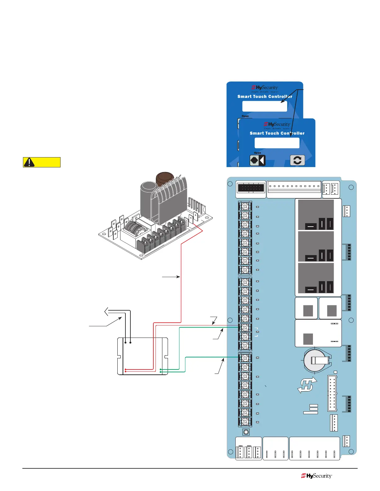
sMart touCh: Wired edGe sensor With GeM (-104)
1. Turn OFF power.
2. Connect the Green NC relay wire from GEM-10 to Sensor 1, 2, or 3.
3. Connect Red & Green wires from GEM-104 to SENSOR COM on Controller (or Power Supply
Board, STC).
4. Connect Red wire from GEM-104 to +24V on Controller
(or Power Supply Board, STC).
5. Connect Black & White wire from GEM to 10K resistor in
edge sensor.
6. Turn ON power and access the Installer Menu. Congure
SENSOR setting accordingly (i.e. Edge Open, Edge
Close, or Edge Both). Refer to Table 4: HySecurity Gate
Operators maintaining Object Detection on page 29.
Black & White
Wires
GEM: Red Wire
GEM:
Green Wire
GEM:
Green Wire
GEM:
Red Wire
Power Supply
Board
Green output wire can attach
to any SENSOR input.
*NOTE: Make sure whichever wired input used (SENSOR 1, 2, or 3) is the
same Sensor # congured through the Installer Menu.
S2 0
SENSOR #2 TYPE
S2 5 (EDGE OPEN)
SENSOR #2 TYPE
Installer Menu
showing Sensor 2
set to Edge Open
(Option #5)*
CAUTION
All external entrapment protection sensors
must be NC sensor outputs and wired to the
SENSOR COM terminal for monitoring and
powering purposes. The sensor becomes
actively powered when the gate operator's
motor runs.
MX3657-01 Rev. D ©2020 Wiring HySecurity Sensors: Smart Touch
hysecurity.com | 800-321-9947 123