MX3657-01 Rev. D ©2020
50 hysecurity.com | 800-321-9947 StrongArm Programming and Operations
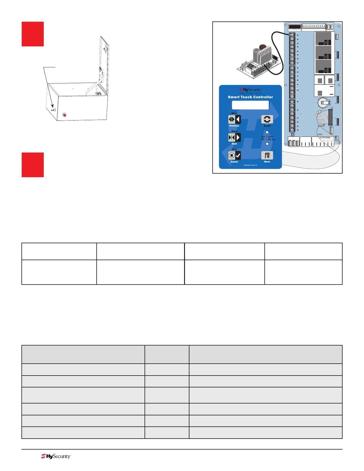
Turn Power ON.
Answer Initial Setup Prompts.
For barrier arms, you will be prompted for USAGE
CLASS and SENSOR 1, SENSOR 2, and SENSOR 3.
Each SENSOR input, whether or not it has a contact or non-contact sensor wired to it, must be programmed to
a non-zero setting before the gate will move.
NOTE: The gate operator will not automatically cycle unless an indication is received that the appropriate number of external
entrapment protection sensors are connected and operational. If your site does not require three sensor inputs, a setting of S1
(NOT USED) must be designated through the Installer Menu for each sensor input (SENSOR 1, SENSOR 2, and SENSOR 3)
STOP BUTTON
OPEN BUTTON
CLOSE BUTTON
REMOTE OPEN AND
RADIO CONTROL
OPEN/CLOSE
1
OPEN PARTIAL
INTERLOCK OPEN
TIME CLOCK OPEN
FREE EXIT DETECTOR
DISABLE EXIT DETECTOR
DISABLE CLOSE TIMER
INSIDE OBSTRUCTION
VEHICLE DETECTOR
OUTSIDE OBSTRUCTION
VEHICLE DETECTOR
SHADOW/RESET
VEHICLE DETECTOR
SENSOR 1
SENSOR COM
DO NOT USE
SENSOR 2
DO NOT USE
SENSOR 3
DO NOT USE
CHARGER
AC LOSS
LOCK INTERLOCK
EMERG CLOSE
FIRE DEPT OPEN
2
3
4
5
6
7
8
9
10
11
12
14
15
16
17
18
19
20
21
22
23
24
Smart Touch Controller
LIMIT DUAL GATE
RADIO OPTIONS
DRIVE
POWER
RS485
MOTOR USER 1
USER 2
USER 3
VEHICLE DETECTORVEHICLE DETECTORVEHICLE DETECTOR
STOP/BUZZER
FREE
EXIT
INSIDE
OBSTR
OUTSIDE
OBSTR
SHADOW
RESET
WIEGAND
HySecurity
COM
NO
MX000585
VERSION
S/N
RS232
DISPLAY
VEHICLE DETECTOR
COM COMA B
RPM
COMOPEN
S 1
+24V +24V
STATU S
LED
24V A
C
A
c
ce
ss
o
ry
power
+ 2
4
V
DC
COMMON
S1 2 (EYE CLOSE)
SENSOR #1 TYPE
I/0 Switch
StrongArm Control Box
Hydraulic
Smart Touch and Smart DC Controller: Menu Mode Navigation Buttons
To change data
appearing in the display
To navigate through
the Selections
To choose what appears
on the display
To navigate between
menu items
Press Select.
Two left characters blink.
Press Next or Previous.
Continue pressing Next to view
all selections.
Press Select.
Blinking characters
become static.
Press Next or Previous.
Advance - press Next
Previous - press Previous
T
able 4: HySecurity Gate Operators maintaining Object Detection
Table 4 indicates those HySecurity gate operators that may be within the exception parameters of UL 325 or
comply with standards other than UL 325, but continue to maintain object detection capabilities. HySecurity
strongly recommends that you assess every site for entrapment zones and provide the necessary protection to
guard against entrapment.
HySecurity Gate Operator's with
Obstruction Protection (Object Detection)
Build Year
UL 325 - 2016
Sensor Inputs automatically set to "NOT USED"
Installer has option to change settings as site design dictates.
StrongArm (HTG) 14, 20, 28, 36 2
●
StrongArmCRASH (M30/M50) 2
●
StrongArmPark DC 10 & DCS 10
StrongArmPark DC 14 & DCS 14
2
●
WedgeSmart DC 10 & 10 DCS 2
●
WedgeSmart DC 14 & 14 DCS 2
●
HydraWedge SM50 2
●
NOTE: NOTE: On the next page,
review LED function and how to
provide temporary power to the
sensors.