MX3657-01 Rev. D ©2020 STC Inputs & Wiring
hysecurity.com | 800-321-9947 79
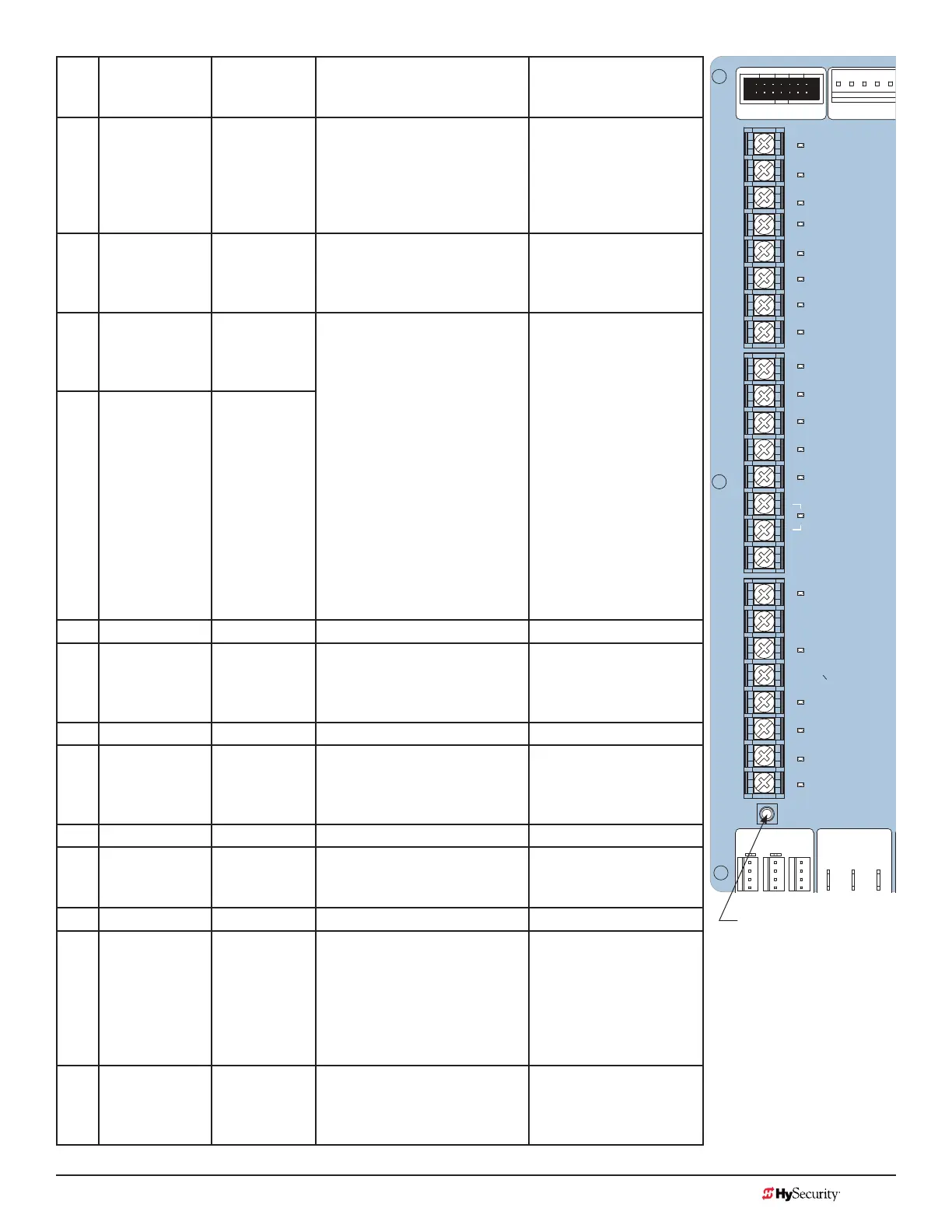
No. Smart Touch
Terminal
UL 325 - 2016
Smart Touch
Terminal
pre-2016
Wire Connections Commonly used for...
7 Interlock Open/
Time Clock
Open LED
Interlock
Open/Time
Clock Open
LED
The default is Interlock Open
(TC 1) but can be congured as
the Time Clock Open
(TC 0) input.
When set to TC1, terminal
used for interlocked
gate input. Set to TC0,
this input provides a
connection to a timer to
open (7-day timer).
13 SENSOR 1 Edge Sensor Refer to Installer Menu: Table 6
on page 66.
Connection to external
entrapment protection
sensors. (Example: photo
eyes or gate edges.)
14 Sensor COM Photo Eye
Power
- 24 Volts
Common
All devices used for entrapment
protection that require
monitoring must be wired to
SENSOR COM.
Refer to How Software Handles
Monitoring External Entrapment
Protection Sensors on page
37 and Wiring HySecurity
Sensors: Smart Touch on page
121.
Device common power
Connect external
entrapment protection
sensors to these
terminals. The sensors
energize only when the
gate operator receives a
run command.
Use these terminals to
preserve battery power.
NOTE: For pre-2016
gate operators, inputs
are labeled as Photo
Eye Power and 24 Volts
Common.
15 Sensor COM Photo Eye
Power
- 24 Volts
Common
16 DO NOT USE DO NOT USE
17 SENSOR 2 Photo
Eye Open
direction
Refer to Installer Menu: Table 6
on page 66.
Connection to external
entrapment protection
sensors. (Example: photo
eyes or gate edges.)
18 DO NOT USE DO NOT USE
19 SENSOR 3 Photo
Eye Close
direction
Refer to Installer Menu: Table
6 on page 66 used for Break
Away Switch if BA is set to 1 in
installer menu.
Connection to external
entrapment protection
sensors. (Example: photo
eyes or gate edges.)
20 DO NOT USE DO NOT USE
21 Charger AC
Loss
Charger AC
Loss
Connection from battery
cabinet.
DC battery cabinet
supplied gate operators
only.
22 Lock Interlock Lock Interlock Refer to user relay option 23. Locking mechanisms.
23 Emergency
Close
Emergency
Close
Activate with +24. Refer to OC
setting in the Installer Menu:
Table 6 on page 66.
Installer menu enabled
and input +24V to trigger.
Requires constant hold
or supervised input.
Overrides photo eyes,
gates edges & vehicle
detectors.
24 Fire Dept Open Fire Dept
Open
Activate with +24. See the
Installer Menu: Table 6 on page
66.
Enable Installer Menu FO
& input +24V to trigger.
Overrides photo eyes and
gates edges.
STOP BUTTON
OPEN BUTTON
CLOSE BUTTON
REMOTE OPEN AND
RADIO CONTROL
OPEN/CLOSE
1
OPEN PARTIAL
INTERLOCK OPEN
TIME CLOCK OPEN
FREE EXIT DETECTOR
DISABLE CLOSE TIMER
INSIDE OBSTRUCTION
VEHICLE DETECTOR
OUTSIDE OBSTRUCTION
VEHICLE DETECTOR
SHADOW/RESET
VEHICLE DETECTOR
SENSOR 1
SENSOR
COM
DO NOT USE
SENSOR 2
DO NOT USE
SENSOR 3
DO NOT USE
CHARGER
AC LOSS
LOCK INTERLOCK
EMERG CLOSE
FIRE DEPT OPEN
2
3
4
5
6
7
8
9
10
11
12
14
15
16
17
18
19
20
21
22
23
24
LIMIT DUAL GATE
DRIVE
COM A B
RPM
LED
Tact Button
STC Inputs