14
7.2 Mounting Surface
The mounting table should have sufficient rigidity to avoid generating vibration.
The surface where the actuator will be mounted should be machined or be equally level and the
flatness tolerance between the actuator and the table should be within 0.05 mm.
Provide enough space around the actuator to permit maintenance work to be done.
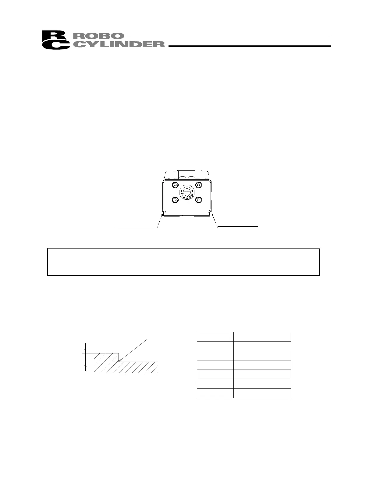
7.2.1 Using Side Faces of the Base as Reference Planes
The side and bottom faces of the actuator base provide the reference planes for slider travel.
When precision is required, use these surfaces as the reference planes for mounting.
Caution: As shown above, the side faces of the base provide the reference planes for slider
travel. When precision is required, use these surfaces as the reference planes for
mounting.
When using the base as the reference planes for mounting the actuator to the machine frame, follow the
machining dimensions shown below.
Type Dimension A
SA4 2 to 3 mm
SA5 2 to 4.5 mm
SA6 2 to 4.5 mm
SA7 2 to 5.5 mm
SS7 2 to 4 mm
SS8 2 to 4.5 mm
(side face of the base)
R0.3 or less
Reference plane
(side face of the base)
Reference plane
For position
adjustment

 Loading...


