21
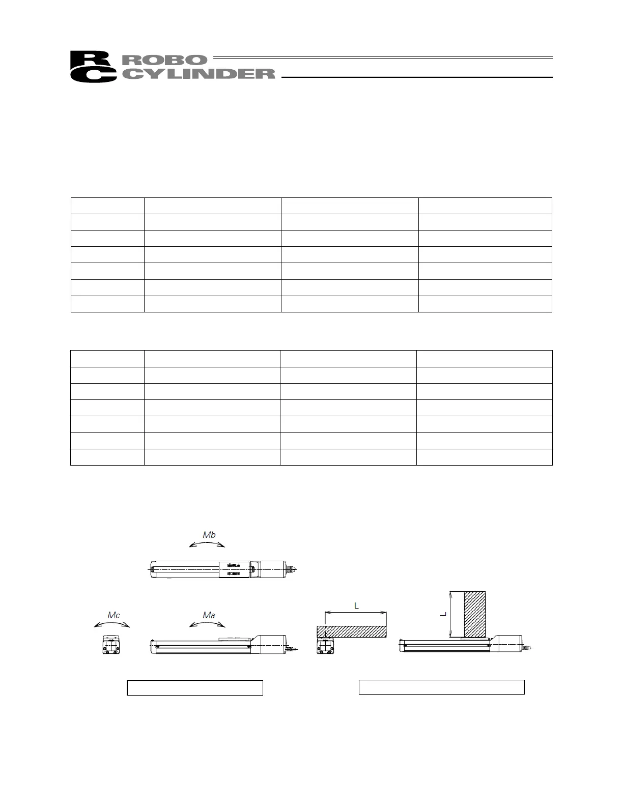
Mb, Mc directions
Ma direction
Directions of moment forces
Directions of allowable overhangs
10. Load on the Actuator
Do not exceed the load shown in the load specification column. Please make note of the slider moment,
allowable overhang length and the load weight.
Load moments
Model Ma Mb Mc
SA4
2.7 Nm (0.27 kgfm) 3.9 Nm (0.4 kgfm) 6.8 Nm (0.7 kgfm)
SA5
4.9 Nm (0.5 kgfm) 6.8 Nm (0.7 kgfm) 11.7 Nm (1.2 kgfm)
SA6
8.9 Nm (0.9 kgfm) 12.7 Nm (1.3 kgfm) 18.6 Nm (1.9 kgfm)
SA7
13.9 Nm (1.41 kgfm) 19.9 Nm (2 kgfm) 38.3 Nm (3.9 kgfm)
SS7
14.7 Nm (1.49 kgfm) 14.7 Nm (1.49 kgfm) 33.3 Nm (3.39 kgfm)
SS8
36.3 Nm (3.7 kgfm) 36.3 Nm (3.7 kgfm) 77.4 Nm (7.89 kgfm)
Allowable overhang lengths
Model Ma direction Mb direction Mc direction
SA4 120 mm or less 120 mm or less 120 mm or less
SA5 150 mm or less 150 mm or less 150 mm or less
SA6 220 mm or less 220 mm or less 220 mm or less
SA7 230 mm or less 230 mm or less 230 mm or less
SS7 300 mm or less 300 mm or less 300 mm or less
SS8 450 mm or less 450 mm or less 450 mm or less
The allowable overhang lengths are based on a configuration where the center of gravity of the load
mounted on the actuator corresponds to the center of the overhang length.

 Loading...


