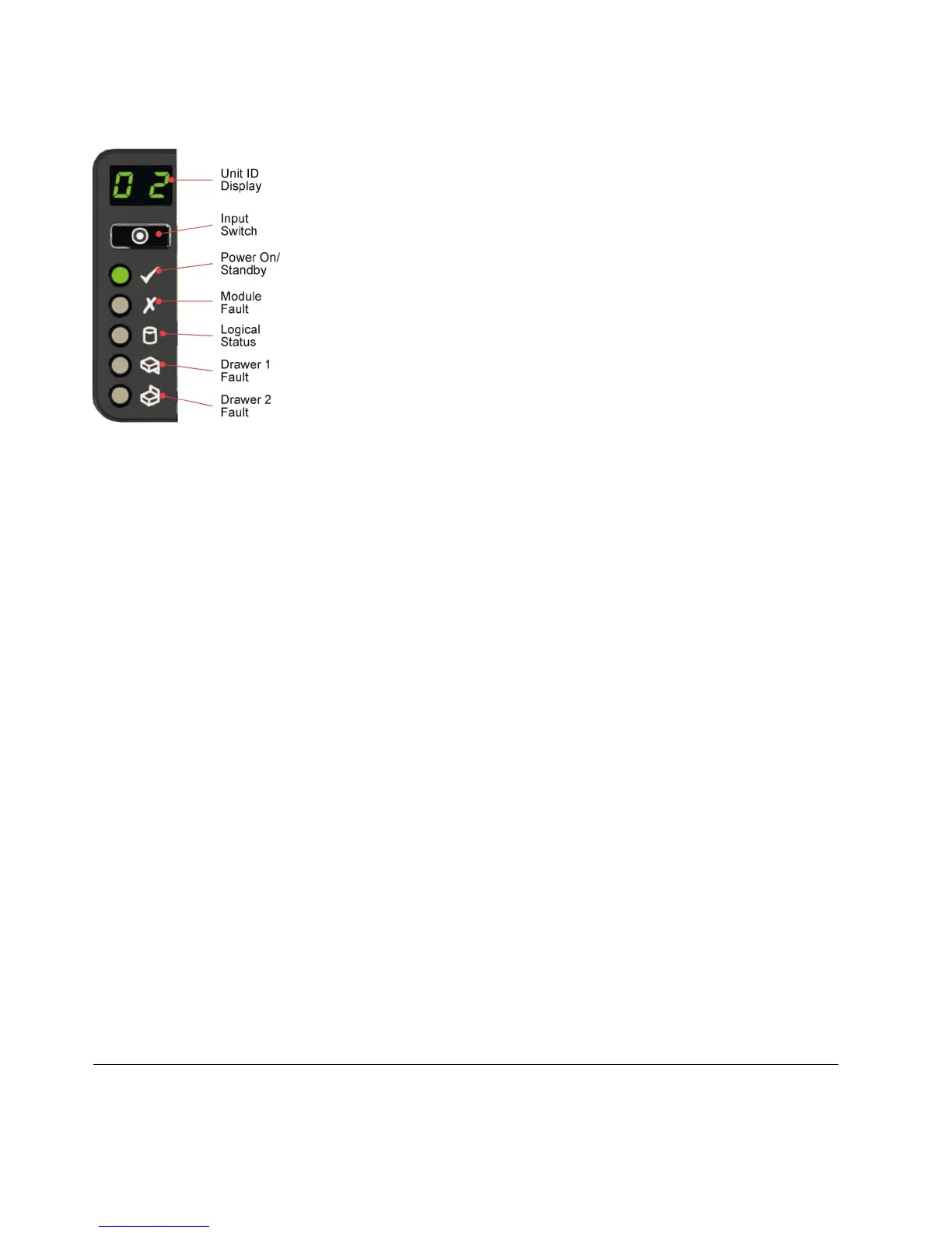
Operator’s panel
The left front of the enclosure features an operator’s (ops) panel (shown in previous figure). The panel
contains the following indicators:
Unit Identification Display
A numerical display whose primary function is to display the enclosure unit identification
number. It can be helpful when setting up and maintaining multiple enclosure systems.
However, a VPD (Vital Product Data) option allows the unit identification display to be
configured for other purposes. The display is on by default and displays a value of 0. See "Unit
Identification Number".
Mute/Input button
Used to set the unit identification display. See "How To Set the Unit Identification Number".
Power On/Standby LED (green/amber)
Shows amber when the system is in standby (not operational). Shows green when the system is
on (operational).
Module Fault LED (amber)
Shows amber when a system hardware fault exists. Additionally, an LED might be lit on a PSU,
drawer, DDIC, cooling module, or compute module that helps you identify which component is
at fault.
Logical Status LED (amber)
Indicates a change of status or fault from something other than the Enclosure Management (EM)
system. It is usually associated with a disk drive and LEDs at each disk drive position help you
identify the drive that is affected.
Drawer 1 Fault LED (amber)
Indicates a drive, cable, or sideplane fault in drawer 1.
Drawer 2 Fault LED (amber)
Indicates a drive, cable, or sideplane fault in drawer 2.
The ops panel is a part of the chassis, and is not replaceable on site.
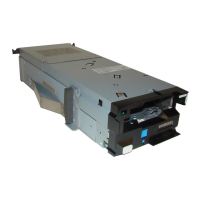
Power supply unit (2200 kW PSU)
Power is provided by two 2200 W PSUs. These units require an input of 200 to 240 VAC at 50 to 60 Hz.
Figure 12. Enclosure operator’s panel
14 Slicestor
®
2584 Appliance Manual
 Loading...