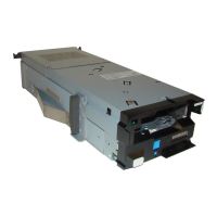
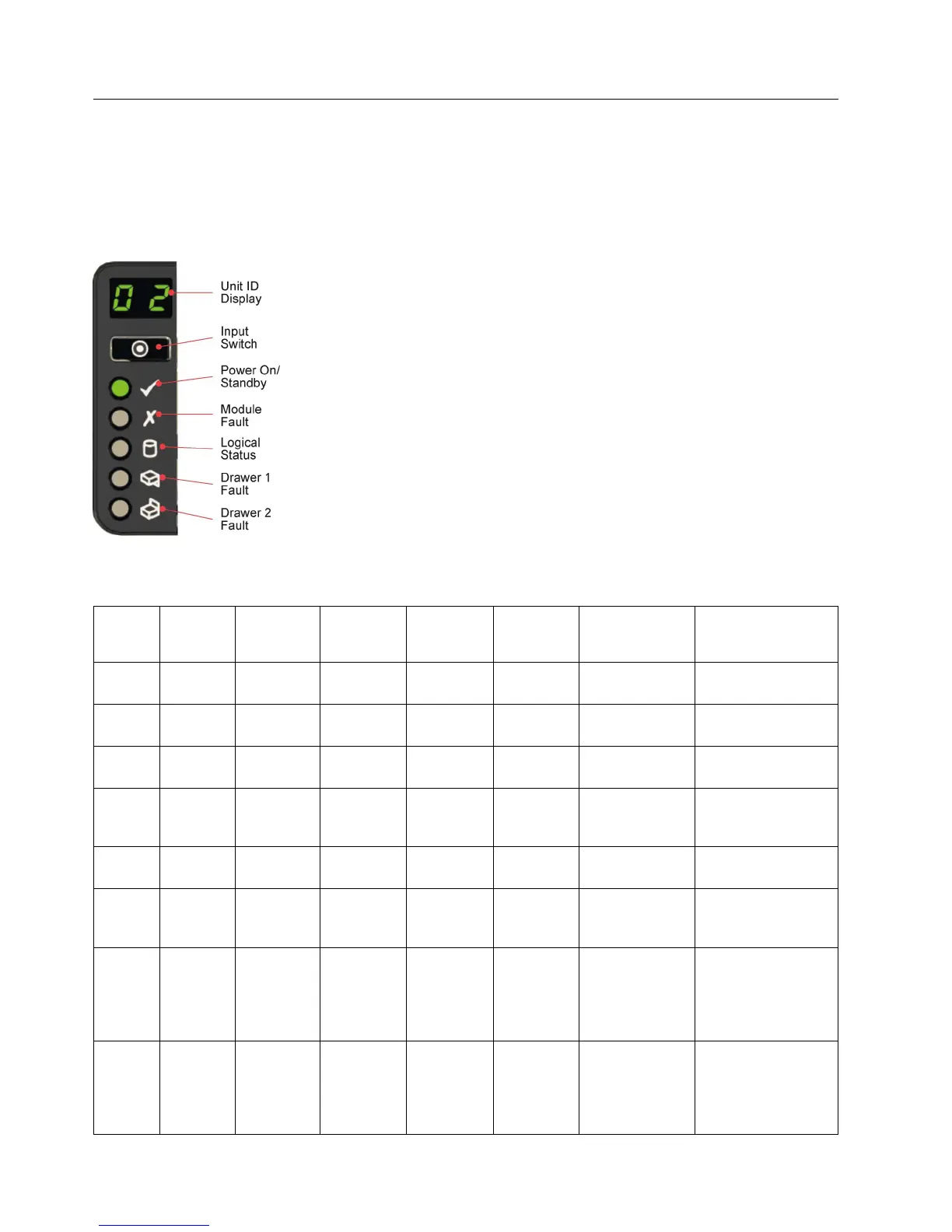
Ops panel LEDs
Ops panel LEDs indicate fault and status conditions.
The following table shows the possible conditions for the LEDs.
The following figure shows the location of the LEDs.
Table 3. Ops panel LED states
Unit ID
display
Power
(green/
amber)
Module
fault
(amber)
Logical
status
(amber)
Drawer 1
fault
Drawer 2
fault
Associated
LEDs or alarms Status
X On Off Off Off Off Aux present, overall
power failed or off
X On On X X X Single beep,
then double
Ops panel power on
(5s) test state
X On Off Off Off Off Power on, all
functions good
X On On X Off Off PSU fault LEDs,
fan fault LEDs
Any PSU fault, fan
fault, over or under
temperature
X On On X Off Off Compute
module LEDs
Any compute
module fault
X On Flashing X Off Off Enclosure logical
fault such as VPD
configuration error
X On Flashing X Off Off Module status
LED on
compute
module
Unknown compute
module type
installed, I2C Bus
failure, or VPD
configuration error
X On Flashing X Off Off PSU fault LEDs,
fan fault LEDs
Unknown (invalid or
mixed) PSU module
type installed, or I2C
Bus failure (PSU
comms)
Figure 25. Ops panel LEDs
28 Slicestor
®
2584 Appliance Manual
 Loading...