EasyManuals Logo

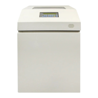
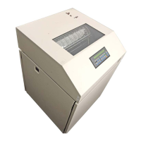
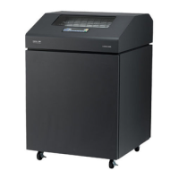
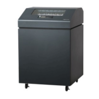
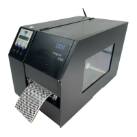
IBM 6400 Series Maintenance Manual

IBM 6400 Series
428 pages
To Next Page IconTo Next Page
To Previous Page IconTo Previous Page
Page #301 background imageLoading...
Page #301 background image
301Wire Data
J1
J13
J12
J14
J5
2–PIN JUMPER
2–PIN JUMPER
2–PIN JUMPER
2–PIN JUMPER
2–PIN JUMPER
J2
EC Diagnostics
1
2
3
SHUT
A
J116
Shuttle Motor
SHUT B
SHUT C
1
2
3
4
5
6
7
8
9
10
J108
Hammer Bank Logic
HMR DAT
HMR DAT RET
HMR CLK
HMR CLK RET
CMD DAT
CMD DAT RET
CMD CLK
CMD CLK RET
TOROID
50 MHz
TOROID
50 MHz
+15V
0.01 mF
10%
50V
Controller, CMX
4.7V
3.0W
DRAM:
72–pin SIMM
J15 = Bank 1
J16 = Bank 0
(See page
224.)
Flash:
80–pin SIMM
J10 = Bank 1
J1
1 = Bank 0
(See page
224.)
1
2
3
4
5
6
7
8
EC DB TXD
9
10
EC DB RXD
FT EVENT
MPU OUT
SHUT DIR
NC
PPR TRIG
PPR MOVING
VCC
10K
1%
0.1W
CAUTION: <5> Do not remove or replace
the NVRAM. The NVRAM contains a
lithium battery that can explode if it is
replaced incorrectly. NVRAM is replaced
only at the factory.
Terminating Resistors
(See page
242.)

Table of Contents

Other manuals for IBM 6400 Series

Questions and Answers:

Question and Answer IconNeed help?

Do you have a question about the IBM 6400 Series and is the answer not in the manual?

IBM 6400 Series Specifications

General IconGeneral
BrandIBM
Model6400 Series
CategoryPrinter
LanguageEnglish

Related product manuals