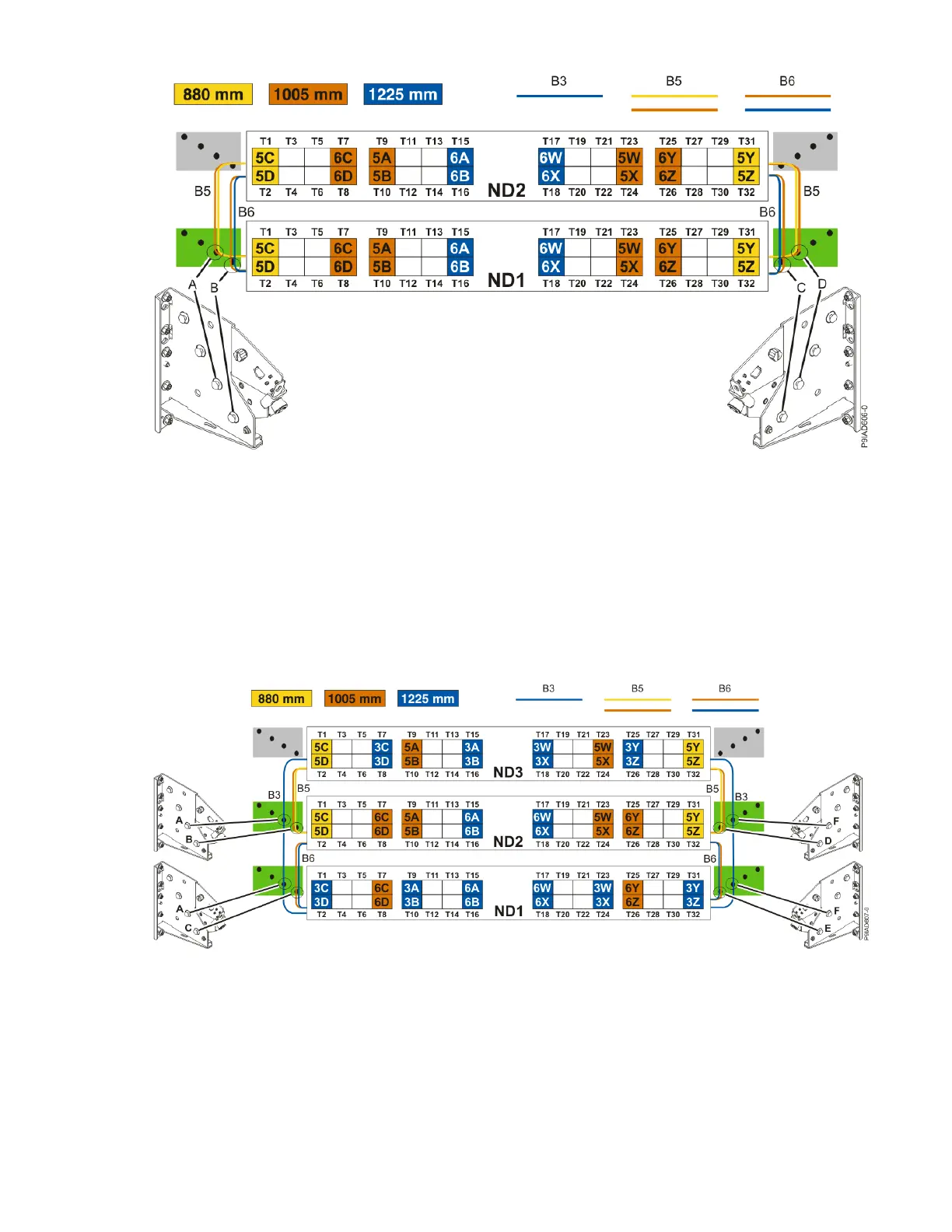
Figure 32. Bundling and connecting SMP cables for two system nodes
• Two bundles named B5 with the "5" cables.
– The left B5 bundle contains 5A, 5B, 5C, and 5D. This bundle attaches to the clip (A).
– The right B5 bundle contains 5W, 5X, 5Y, and 5Z. This bundle attaches to the clip (D).
• Two bundles named B6 with the "6"cables.
– The left B6 bundle contains 6A, 6B, 6C, and 6D. This bundle attaches to the clip (B).
– The right B6 bundle contains 6W, 6X, 6Y, and 6Z. This bundle attaches to the clip (C).
Three system node conguration: The three system node conguration has four cable bundles.
Figure 33. Bundling and connecting SMP cables for three system nodes
• Two bundles named B3 with the "3" cables.
– The left B3 bundle contains 3A, 3B, 3C, and 3D. This bundle attaches to the clip (A).
– The right B3 bundle contains 3W, 3X, 3Y, and 3Z. This bundle attaches to the clip (F).
• Two bundles named B5 with the "5" cables.
– The left B5 bundle contains 5A, 5B, 5C, and 5D. This bundle attaches to the clips (B).
– The right B5 bundle contains 5W, 5X, 5Y, and 5Z. This bundle attaches to the clip (D).
40
Power Systems: Removing and replacing parts in the 9080-M9S system

 Loading...