82 IBM eX5 Implementation Guide
MAX5 configurations
The memory installed in the MAX5 operates at the same speed as the memory that is
installed in the x3850 X5 server. As explained in 2.3.1, “Memory speed” on page 22, the
memory speed is derived from the QPI link speed of the installed processors, which in turn
dictates the maximum SMI link speed, which in turn dictates the memory speed.
Table 3-9 on page 74 summarizes the memory speeds of all the models of Intel Xeon 7500
series CPUs.
One important consideration when installing memory in MAX5 configurations is that the
server must be fully populated before adding DIMMs to the MAX5. As we described in 2.3.2,
“Memory DIMM placement” on page 23, you get the best performance by using all memory
buffers and all DIMM sockets on the server first, and then add DIMMs to the MAX5.
Figure 3-18 on page 83 shows the numbering scheme for the DIMM slots on the MAX5, and
the pairing of DIMMs in the MAX5. As DIMMs are added in pairs, they must be matched on a
memory port (as shown by using the colors). For example, DIMM1 is matched to DIMM 8,
DIMM 2 to DIMM 7, DIMM 20 to DIMM 21, and so on.
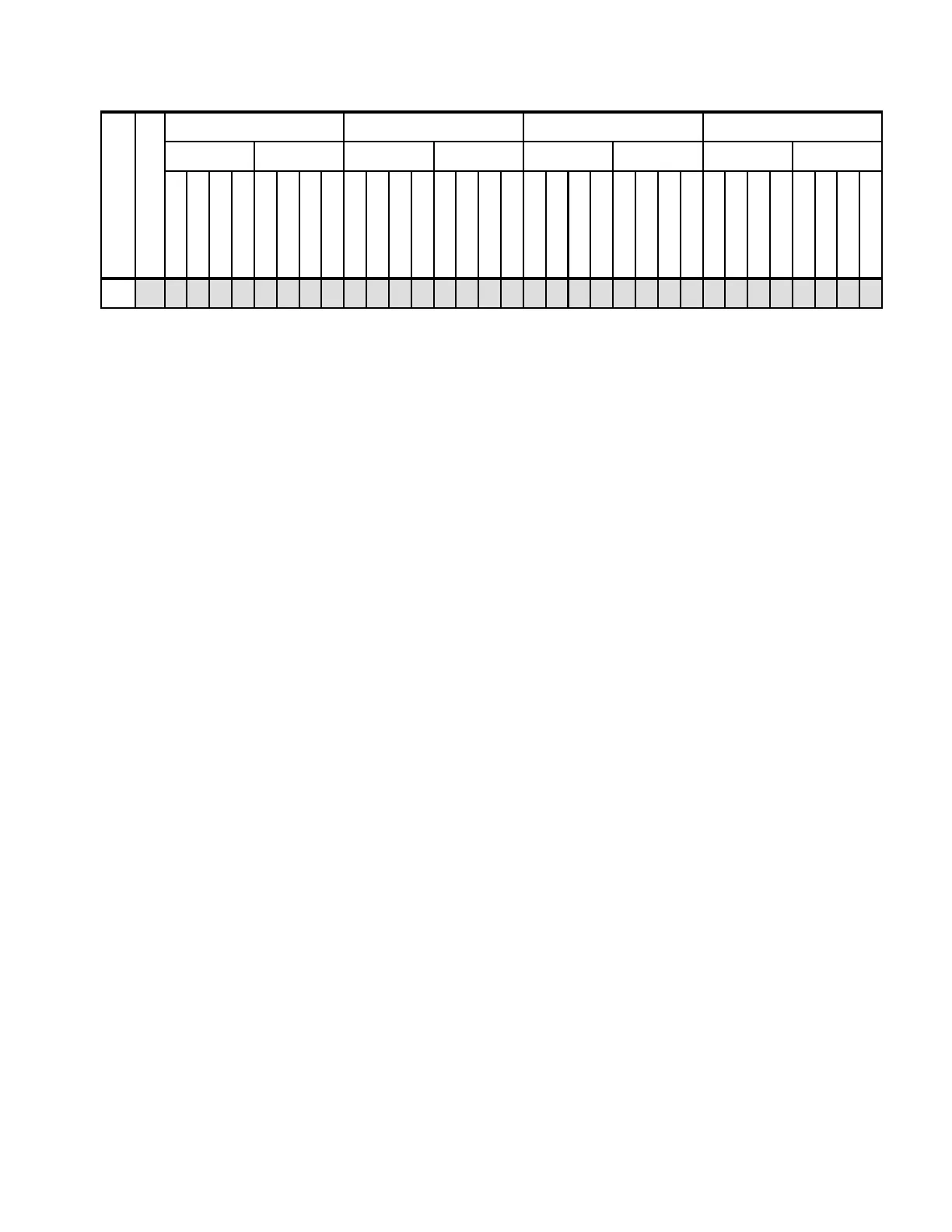
64 Y x x x x x x x x x x x x x x x x x x x x x x x x x x x x x x x x
a. For more information about Hemisphere Mode and its importance, see 2.3.5, “Hemisphere Mode” on page 26.
Number of DIMMs
Hemisphere Mode
a
Processor 1 Processor 4 Processor 2 Processor 3
Card 1Card 2Card 7Card 8Card 3Card 4Card 5Card 6
DIMM 1 and 8
DIMM 3 and 6
DIMM 2 and 7
DIMM 4 and 5
DIMM 1 and 8
DIMM 3 and 6
DIMM 2 and 7
DIMM 4 and 5
DIMM 1 and 8
DIMM 3 and 6
DIMM 2 and 7
DIMM 4 and 5
DIMM 1 and 8
DIMM 3 and 6
DIMM 2 and 7
DIMM 4 and 5
DIMM 1 and 8
DIMM 3 and 6
DIMM 2 and 7
DIMM 4 and 5
DIMM 1 and 8
DIMM 3 and 6
DIMM 2 and 7
DIMM 4 and 5
DIMM 1 and 8
DIMM 3 and 6
DIMM 2 and 7
DIMM 4 and 5
DIMM 1 and 8
DIMM 3 and 6
DIMM 2 and 7
DIMM 4 and 5
 Loading...