Chapter 3. IBM System x3850 X5 and x3950 X5 83
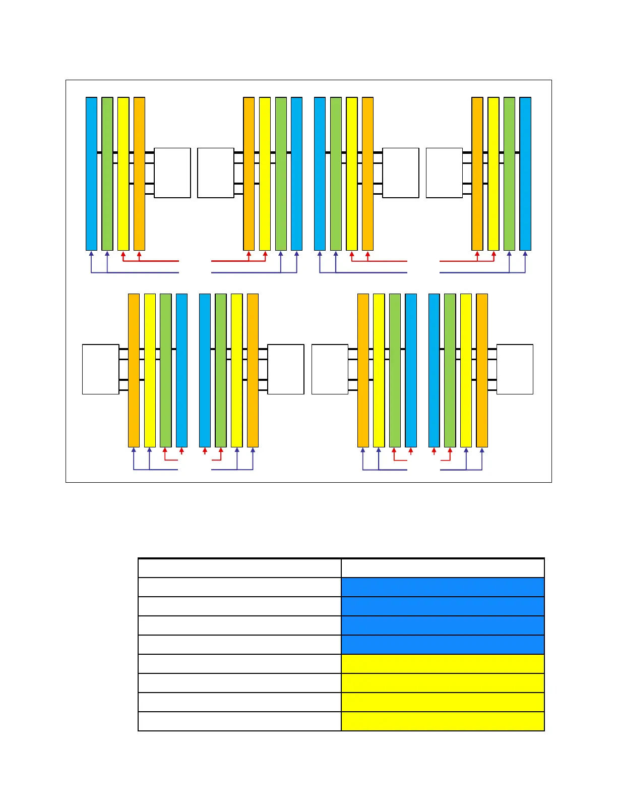
Figure 3-18 DIMM numbering on MAX5
Table 3-16 shows the population order of the MAX5 DIMM slots, ensuring that memory is
balanced among the memory buffers. The colors in the table match the colors in Figure 3-18.
Table 3-16 DIMM installation sequence in the MAX5
0
1
0
1
0
1
16 15 14 13
Memory
buffer
3
12 11 10 9 8 7 6 5
Memory
buffer
5
Memory
buffer
6
4321
0
1
Memory
buffer
4
0
1
0
1
Memory
buffer
1
DIMM 29
DIMM 30
DIMM 31
DIMM 32
32 31 30 29
DIMM 28
DIMM 27
DIMM 26
DIMM 25
28 27 26 25
Memory
buffer
2
0
1
0
1
Memory
buffer
8
DIMM 21
DIMM 22
DIMM 23
DIMM 24
24 23 22 21
DIMM 20
DIMM 19
DIMM 18
DIMM 17
20 19 18 17
Memory
buffer
7
DIMM 9
DIMM 10
DIMM 11
DIMM 12
DIMM 16
DIMM 15
DIMM 14
DIMM 13
DIMM 6
DIMM 5
DIMM 3
DIMM 4
DIMM 8
DIMM 7
DIMM 1
DIMM 2
Quad D
Quad C
Quad B
Quad A
Quad G
Quad H
Quad E
Quad F
DIMM pair DIMM slots
1
28 and 29
2
9 and 16
3
1 and 8
4
20 and 21
5
26 and 31
6
11 and 14
7
3 and 6
8
18 and 23
 Loading...