198 IBM eX5 Implementation Guide
MAX5 memory population order
With the configuration of an HX5 connected to a MAX5, follow these rules:
Install at least two DIMMs in the HX5 (four DIMMs if the HX5 has two installed
processors).
For the best memory performance, fully populate the HX5 by using the sequence that is
listed in Table 5-14 on page 197, and then populate the MAX5 by using the sequence that
is listed in Table 5-16 on page 199.
The data widths for the following quads must match. For example, DIMMs in each quad
must be all 4Rx8 or all 2Rx8. See Figure 5-15 for the block diagram and Figure 5-14 on
page 196 for the physical location of these DIMMs.
– DIMMs 1, 2, 7, and 8
– DIMMs 3, 4, 5, and 6
– DIMMs 13, 14, 17, and 18
– DIMMs 15, 16, 19, and 20
– DIMMs 9, 10, 21, and 22
– DIMMs 11, 12, 23, and 24
Based on the two DIMM options that are currently supported in the MAX5 (listed in
Table 5-13 on page 194), this step means that all DIMMs in each of the quads listed here
must be either 4 GB or 8 GB. You cannot mix 4 GB and 8 GB DIMMs in the same quad.
Memory must be installed in matched pairs of DIMMs in the MAX5.
Memory DIMMs must be installed in the order of DIMM size with largest DIMMs first. For
example, if you plan to install both 4 GB and 8 GB DIMMs into the MAX5, use the
population order that is listed in Table 5-16 on page 199. Install all 8 GB DIMMs first, and
then install the 4 GB DIMMs.
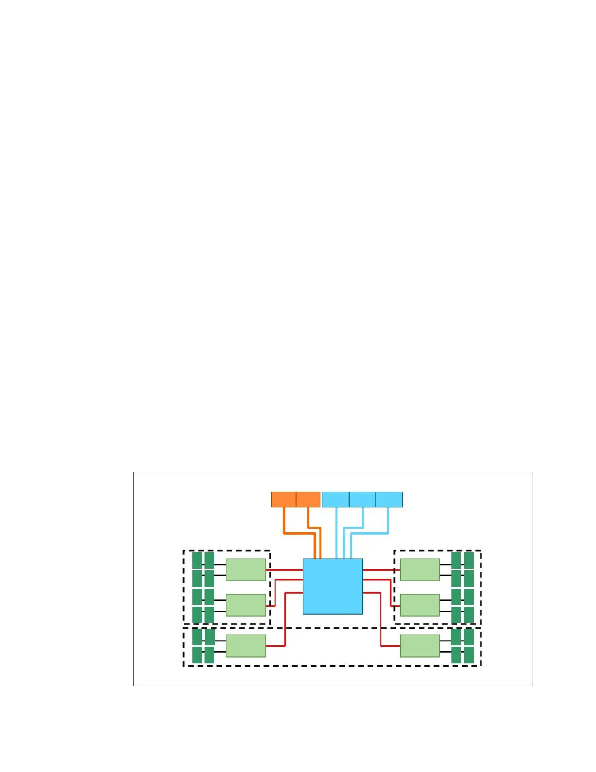
The DIMM sockets in the MAX5 are arranged in three power domains (A, B, and C), as shown
in Figure 5-15. Each power domain includes two memory controllers and eight DIMM sockets.
Figure 5-15 Power domains in the MAX5 memory expansion blade
a. For more information about Hemisphere Mode and its importance, see 2.3.5, “Hemisphere
Mode” on page 26
Logical connectors to HX5 blades
SMI
links
12
34
Memory
buffer
56
78
Memory
buffer
109
1112
Memory
buffer
QPIQPI EXA EXAEXA
14 13
16 15
Memory
buffer
20 19
18 17
Memory
buffer
23 24
21 22
Memory
buffer
IBM EXA
chip
Power domain A Power domain B
Power domain C
 Loading...