76 IBM Midrange System Storage Hardware Guide
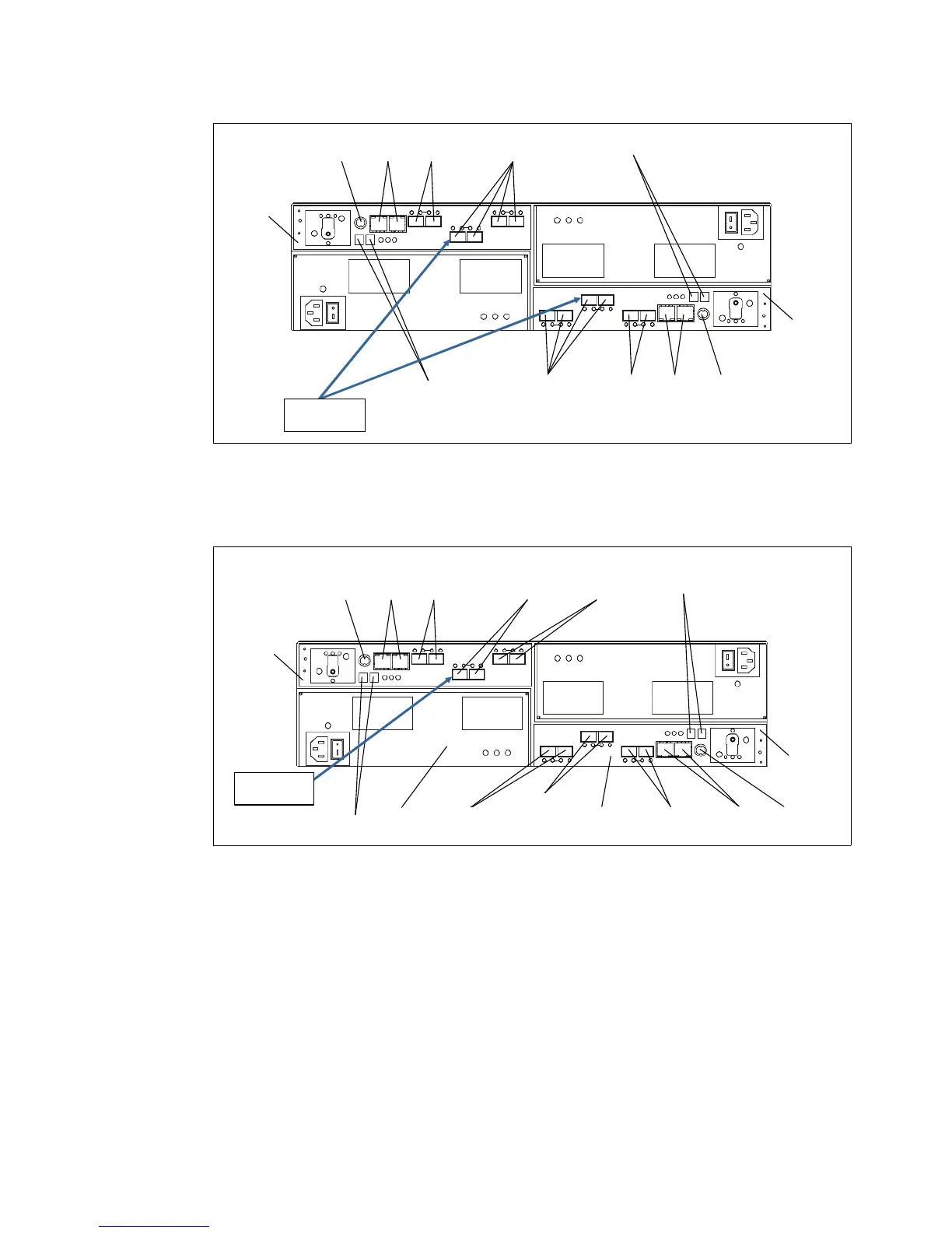
Figure 3-52 DS5020 rear view: 8 FC Port model
Another configuration of the DS5020 has additional four 8 Gbps FC host ports (Figure 3-52)
or additional four 1 Gbps iSCSI host ports instead (Figure 3-53).
Figure 3-53 DS5020 rear view: 4 FC and 4 iSCSI port model
The DS5020 rear view shows four hot swappable parts:
The two controllers with the Backup Battery Unit (BBU)
The two Power Supply and Fan Units
The two controllers hold host and drive interfaces as well as the batteries. The left controller is
controller A and the right controller is controller B. Note that controller A is upside-down
relative to controller B. The same configuration applies to the power supply and fan unit. It is
important to keep this information in mind when connecting the back-end ports to hosts and
drive-side expansion enclosures. Refer to 3.5.7, “DS5020 storage subsystem drive-side
connections” on page 85 for more details.
Controller A
Serial
port
Ethernet
ports
Dual-ported
drive channel
Fibre Channel
host channels
Enclosure ID
Controller B
Serial
port
Ethernet
ports
Dual-ported
drive channel
Fibre Channel
host channels
Enclosure ID
Optional FC
HIC installed
Controller A
Serial
port
Ethernet
ports
Dual-ported
drive channel
Fibre Channel
host channels
Enclosure ID
Controller B
iSCSI
host
channels
Serial
port
Ethernet
ports
Dual-ported
drive channel
Fibre Channel
host channels
Enclosure ID
iSCSI
host
channels
Power-fan
canister
Controller
canister
Optional FC
HIC installed

 Loading...


