70 IBM Midrange System Storage Hardware Guide
3.5.2 DS5020 components
Figure 3-44 shows the subcomponents of the DS5020 storage subsystem.
Figure 3-44 DS5020 hardware components
AC power supply and fan unit
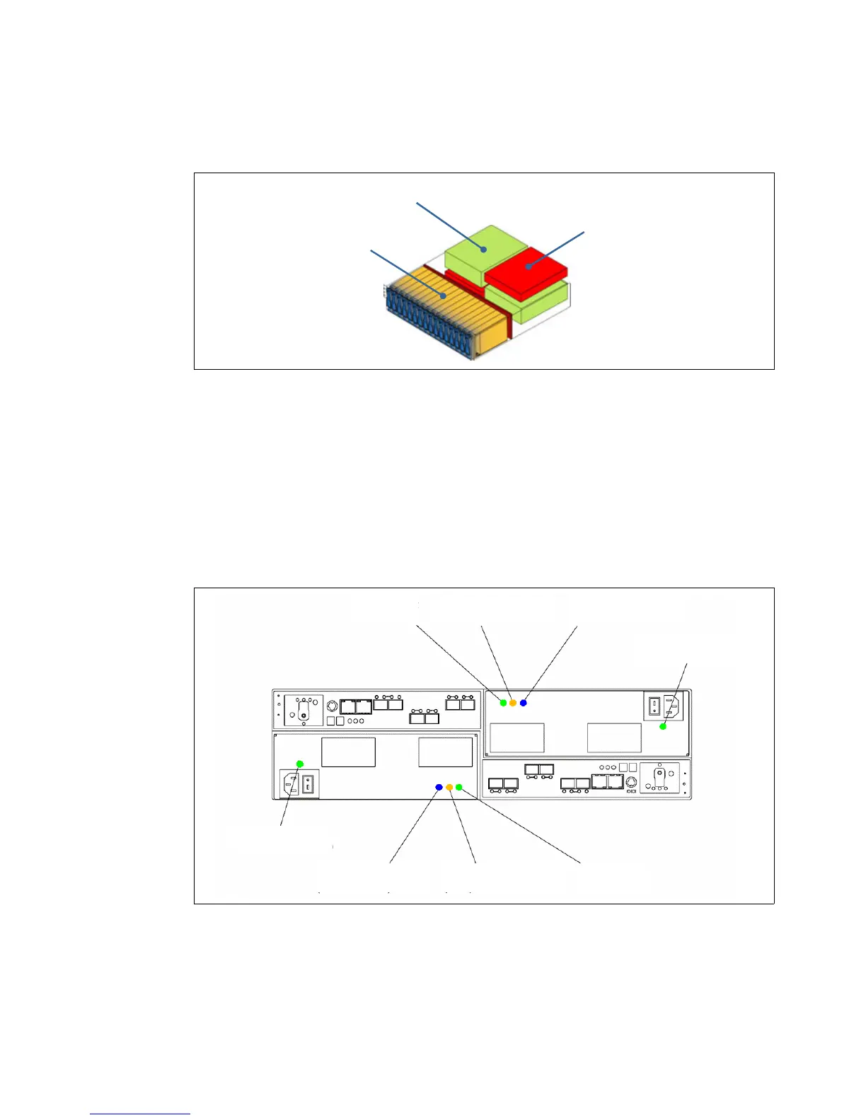
Figure 3-45 shows the LEDs on the AC power supply and fan unit.
The LEDs display the status of the storage subsystem and components. The color of the LED
is important:
Green LEDs indicate a normal operating status.
Amber LEDs (Needs Attention) indicate a possible failure.
A blue LEDs on a CRU indicates that it is safe to remove the component.
Figure 3-45 DS5020 power supply and fan unit LEDs
In normal operation, only the green LEDs (power LED and DC enabled LED) are on.
Drives
Power/cooling
Controllers
Direct current
enabled LED
Service action required
(fault) LED
Service action allowed
(ok to remove) LED
Power supply and
fan unit power LED
Direct current
enabled LED
Service action required
(fault) LED
Service action allowed
(ok to remove) LED
Power supply and
fan unit power LED

 Loading...


