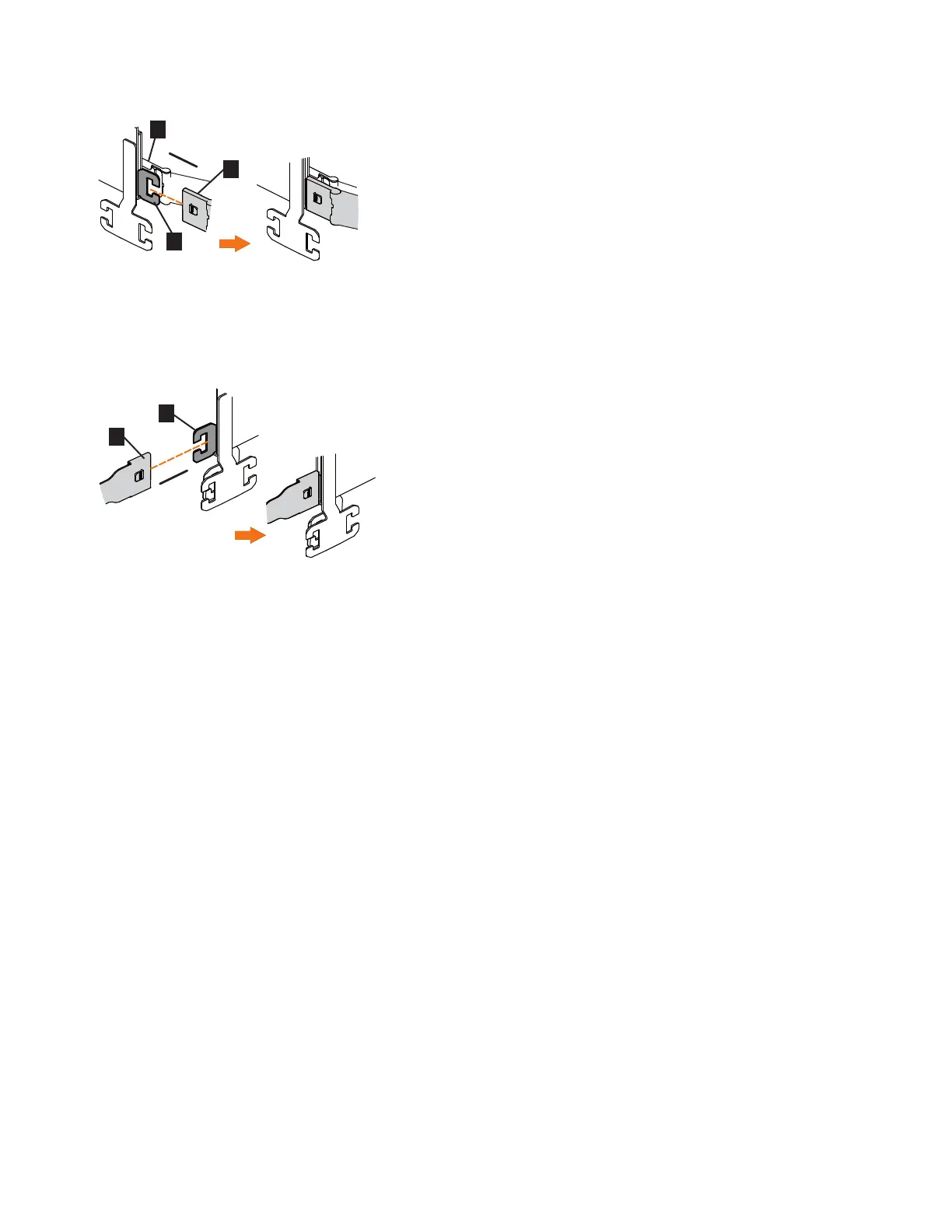
4. Attach the support rail connector on the upper CMA assembly (▌5▐) to the
connector base on the right support rail (▌6▐), as shown in Figure 73.
Ensure the cable-management arm connector attaches securely to the hooks on
the rails.
Installing the lower CMA assembly
Note: The procedure for attaching the lower CMA assembly is the same as the
procedure to attach the upper CMA assembly. However, the connector locations are
reversed. For comparison, Figure 74 on page 79 shows the upper and lower CMA
assemblies as they are aligned to the support rails. The support rail connector of
the upper CMA attaches to the right rail. The support rail connector of the lower
CMA ▌11▐ attaches to the left rail.
Figure 72. Install the inner connector of the upper CMA to the inner member of the support rail
Figure 73. Attach the support rail connector of the upper CMA to the right support rail
78 SAN Volume Controller: Model 2145-SV1 Hardware Installation Guide
 Loading...