2. When you replace the system board, you must either update the server with the
latest firmware or restore the pre-existing firmware that the customer provides
on a diskette or CD image. Make sure that you have the latest firmware or a
copy of the pre-existing firmware before you proceed. See “Updating the
firmware” on page 253, “Updating the Universal Unique Identifier (UUID)” on
page 271, and “Updating the DMI/SMBIOS data” on page 274 for more
information.
Important: Some cluster solutions require specific code levels or coordinated
code updates. If the device is part of a cluster solution, verify that the latest
level of code is supported for the cluster solution before you update the code.
3. Update the vital product data (VPD) through the server firmware update
procedure.
4. If you see the error message Non-compatible/non-supported CPU, see PDSG
for more information appears, the microprocessor that you installed is not
supported. See Chapter 4, “Parts listing, Types 4255, 7945, and 7949 server,”
on page 157 for a list of supported microprocessors.
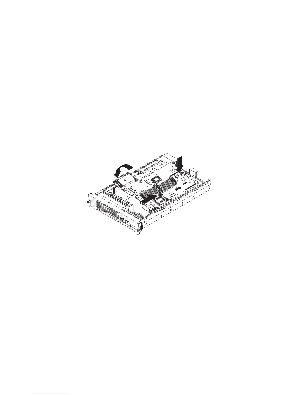
To reinstall the system board, complete the following steps.
1. Align the system board at an angle, as shown in the illustration; then, rotate
and lower it flat and slide it back toward the rear of the server. Make sure that
the rear connectors extend through the rear of the chassis.
2. Reconnect to the system board the cables that you disconnected in step 11 of
“Removing the system board” on page 247 (see “Internal cable routing and
connectors” on page 172).
3. Rotate the system-board release latch toward the rear of the server until the
latch clicks into place.
4. Install the fans.
5. Install each microprocessor with its matching heat sink (see “Installing a
microprocessor and heat sink” on page 240).
6. Install the DIMMs (see “Installing a memory module” on page 217).
7. Install the air baffles (see “Installing the DIMM air baffle” on page 182) and
“Removing the microprocessor 2 air baffle” on page 178, making sure that all
cables are out of the way.
8. Install the SAS riser-card and controller assembly (see “Installing the SAS
riser-card and controller assembly” on page 198).
9. If necessary, install the Ethernet adapter.
10. If necessary, install the virtual media key.
Chapter 5. Removing and replacing server components 249

 Loading...


