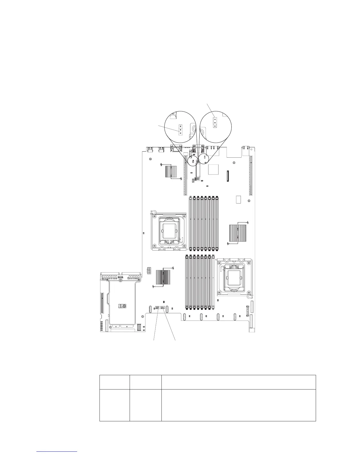
System-board switches and jumpers
The following illustration shows the location and description of the switches and
jumpers.
Note: If there is a clear protective sticker on the top of the switch blocks, you must
remove and discard it to access the switches.
The default positions for the UEFI and the IMM recovery jumpers are pins 1 and 2.
SW3 switch blockSW4 switch block
UEFI boot recovery
jumper (J29)
1
2
3
1
2
3
IMM recovery jumper
(J147)
The following table describes the jumper settings for J29 and J147 on the system
board.
Table 2. System board jumpers
Jumper
number
Jumper
name Jumper setting
J29 UEFI boot
recovery
jumper
v Pins 1 and 2: Normal (default) Loads the primary server
firmware ROM page.
v Pins 2 and 3: Loads the secondary (backup) server firmware
ROM page.
Chapter 2. Introduction 17

 Loading...


