DIMM 17
DIMM 16
DIMM 15
DIMM 14
DIMM 13
DIMM 12
DIMM 11
DIMM 10
DIMM 8
DIMM 7
DIMM 6
DIMM 5
DIMM 4
DIMM 3
DIMM 2
DIMM 1
CH2
CH1
CH0
CH2
CH1
CH0
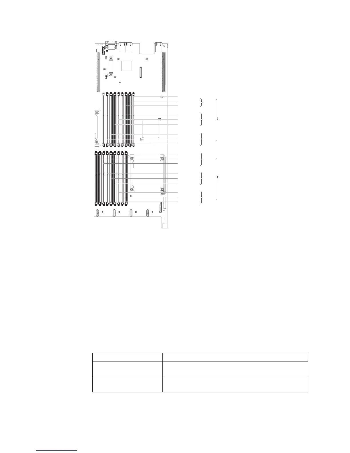
Microprocessor 2
Microprocessor 1
DIMM 9
DIMM 18
DIMM installation sequence
The server comes with a minimum of one 2 GB DIMM installed in slot 3. When you
install additional DIMMs, install them in the order shown in the following table to
optimize system performance. In non-mirroring mode, all three channels on the
memory interface for each microprocessor can be populated in any order and have
no matching requirements. When you install additional DIMMs, install them in the
order shown in the following table, to maintain performance.
You can install DIMMs for microprocessor 2 as soon as microprocessor 2 is
installed. You are not required to fill all the DIMM connectors for microprocessor 1
first.
Important: If you have configured the server to use memory mirroring, do not use
the order in Table 16; go to Table 17 on page 221 and Table 18 on page 221 for
memory mirroring and use the installation order shown there.
Table 16. DIMM installation sequence
Installed microprocessors DIMM connector population sequence
Microprocessor socket 1 Install the DIMMs in the following sequence: 3, 6, 9, 2, 5, 8,
1, 4, 7
Microprocessor socket 2 Install the DIMMs in the following sequence: 12, 15, 18, 11,
14, 17, 10, 13, 16
220 IBM System x3650 M3 Types 4255, 7945, and 7949: Problem Determination and Service Guide

 Loading...


