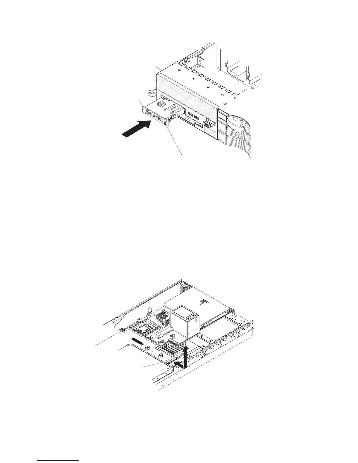
Release latch
Operator information
panel
1. From the front of the server, thread the operator-information-panel ribbon cable
through the panel housing in the server; then, connect the ribbon cable to the
operator-panel connector (J50) on the system board (see “System-board
internal cable connectors” on page 11 for the location of the connector).
2. Slide the panel into the server until it clicks into place.
3. Inside the server, secure the ribbon cable to the top of the panel enclosure,
using the hook-and-loop fastener.
4. Install the cover (see “Installing the cover” on page 91).
5. Slide the server into the rack.
6. Reconnect the external cables; then, reconnect the power cords and turn on the
peripheral devices and the server.
Removing the power backplane
To remove the power backplane, complete the following steps.
Power backplane
connector
1. Read the safety information that begins on page vii and “Installation guidelines”
on page 87.
2. Turn off the server and peripheral devices, and disconnect the power cords and
all external cables.
126 IBM System x3650 Type 7979 and 1914: Problem Determination and Service Guide

 Loading...


