v Follow the suggested actions in the order in which they are listed in the Action column until the problem
is solved.
v See Chapter 3, “Parts listing, Type 7979 and 1914 server,” on page 79 to determine which components are
customer replaceable units (CRU) and which components are field replaceable units (FRU).
v If an action step is preceded by “(Trained service technician only),” that step must be performed only by a
trained service technician.
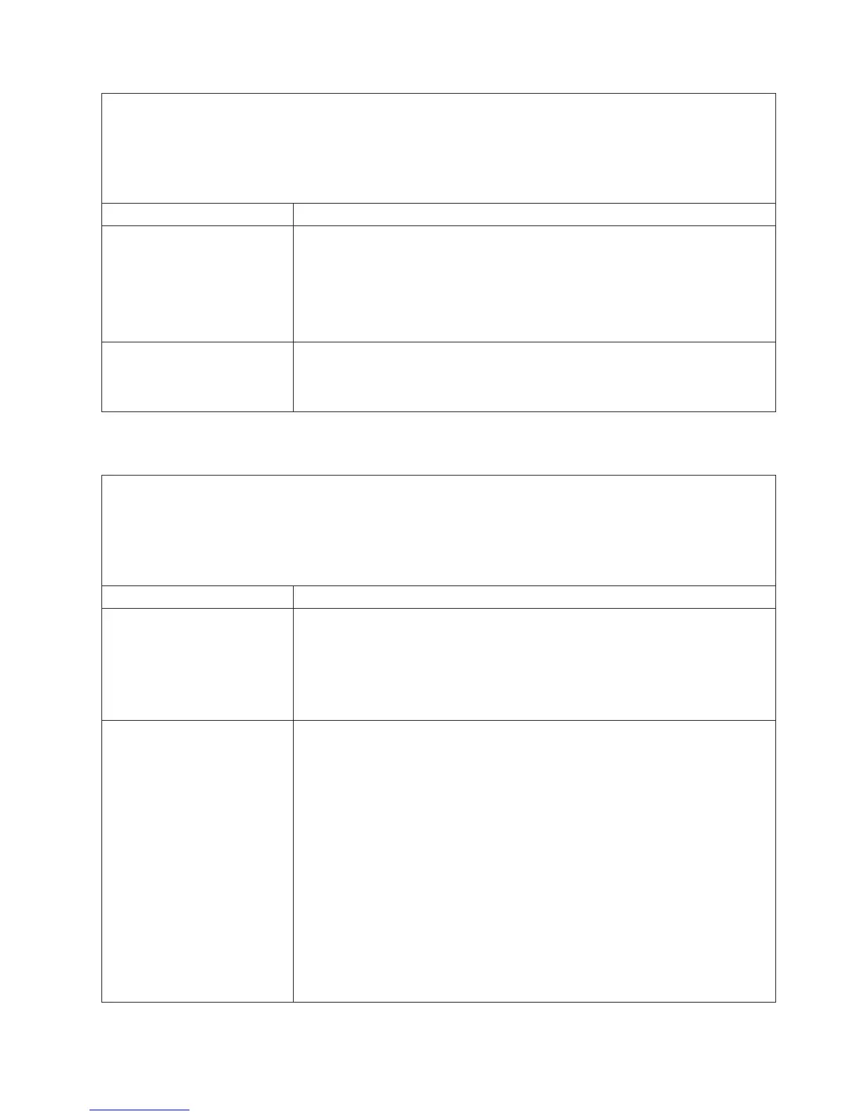
Symptom Action
The server does not turn off.
1. Turn off the server by pressing the power-control button for 5 seconds.
2. Restart the server.
3. If the server fails POST and the power-control button does not work, disconnect
the ac power cord for 20 seconds; then, reconnect the ac power cord and
restart the server.
4. If the problem remains, suspect the system board.
The server unexpectedly shuts
down, and the LEDs on the
operator information panel are
not lit.
See “Solving undetermined problems” on page 76.
Serial port problems
v Follow the suggested actions in the order in which they are listed in the Action column until the problem
is solved.
v See Chapter 3, “Parts listing, Type 7979 and 1914 server,” on page 79 to determine which components are
customer replaceable units (CRU) and which components are field replaceable units (FRU).
v If an action step is preceded by “(Trained service technician only),” that step must be performed only by a
trained service technician.
Symptom Action
The number of serial ports that
are identified by the operating
system is less than the number
of installed serial ports.
1. Make sure that:
v Each port is assigned a unique address in the Configuration/Setup Utility
program and none of the serial ports is disabled.
v The serial-port adapter (if one is present) is seated correctly.
2.
Reseat the serial port adapter, if one is present.
3. Replace the serial port adapter, if one is present.
A serial device does not work.
1. Make sure that:
v The device is compatible with the server.
v The serial port is enabled and is assigned a unique address.
v The device is connected to the correct connector (see “Rear view” on page
7).
2.
Reseat the following components:
a. Failing serial device
b. Serial cable
c. Remote Supervisor Adapter II SlimLine (if one is present)
3.
Replace the following components one at a time, in the order shown, restarting
the server each time:
a. Failing serial device
b. Serial cable
c. Remote Supervisor Adapter II (if one is present)
d. (Trained service technician only) System board
Chapter 2. Diagnostics 47