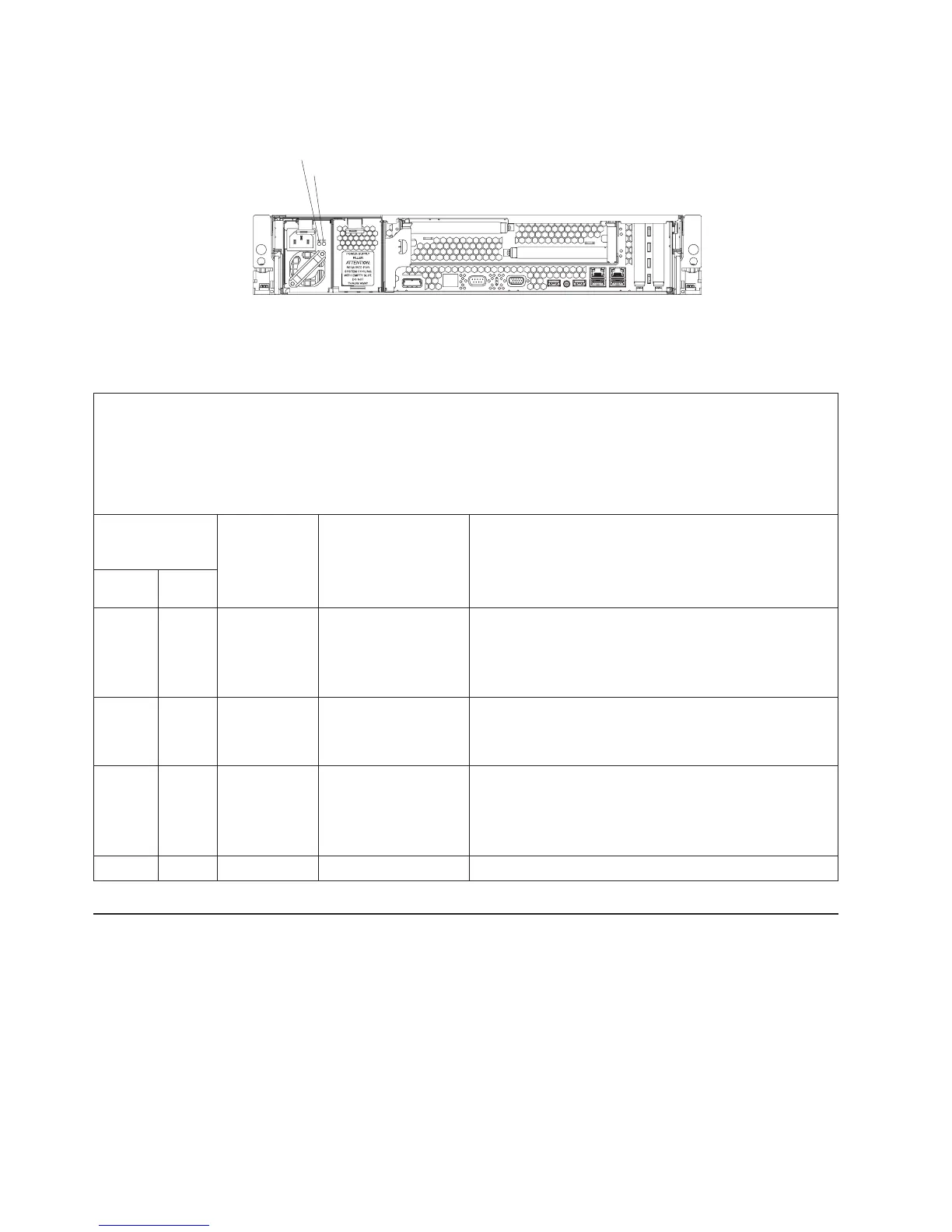
The following illustration shows the locations of the power-supply LEDs.
AC power LED
DC power LED
The following table describes the problems that are indicated by various
combinations of the power-supply LEDs and the power-on LED on the operator
information panel and suggested actions to correct the detected problems.
v Follow the suggested actions in the order in which they are listed in the Action column until the problem
is solved.
v See Chapter 3, “Parts listing, Type 7979 and 1914 server,” on page 79 to determine which components are
customer replaceable units (CRU) and which components are field replaceable units (FRU).
v If an action step is preceded by “(Trained service technician only),” that step must be performed only by a
trained service technician.
Power-supply
LEDs
Operator
information
panel
power-on
LED
Description Action AC DC
Off Off Off No power to the
server, or a problem
with the ac power
source.
1. Check the ac power to the server.
2. Make sure that the power cord is connected to a
functioning power source.
3. Remove one power supply at a time.
Lit Off Off DC source power
problem.
1. Remove one power supply at a time.
2. View the system error logs (see “Error logs” on page
26).
Lit Lit Off Standby power
problem.
1. View the system error logs (see “Error logs” on page
26).
2. Remove one power supply at a time.
3. Replace the power backplane.
Lit Lit Lit The power is good. No action is necessary.
Diagnostic programs, messages, and error codes
The diagnostic programs are the primary method of testing the major components
of the server. As you run the diagnostic programs, text messages and error codes
are displayed on the screen and are saved in the test log. A diagnostic text
message or error code indicates that a problem has been detected; to determine
what action you should take as a result of a message or error code, see the table in
“Diagnostic error codes” on page 56.
54 IBM System x3650 Type 7979 and 1914: Problem Determination and Service Guide