v Follow the suggested actions in the order in which they are listed in the Action column until the problem
is solved.
v See Chapter 3, “Parts listing, Type 7979 and 1914 server,” on page 79 to determine which components are
customer replaceable units (CRU) and which components are field replaceable units (FRU).
v If an action step is preceded by “(Trained service technician only),” that step must be performed only by a
trained service technician.
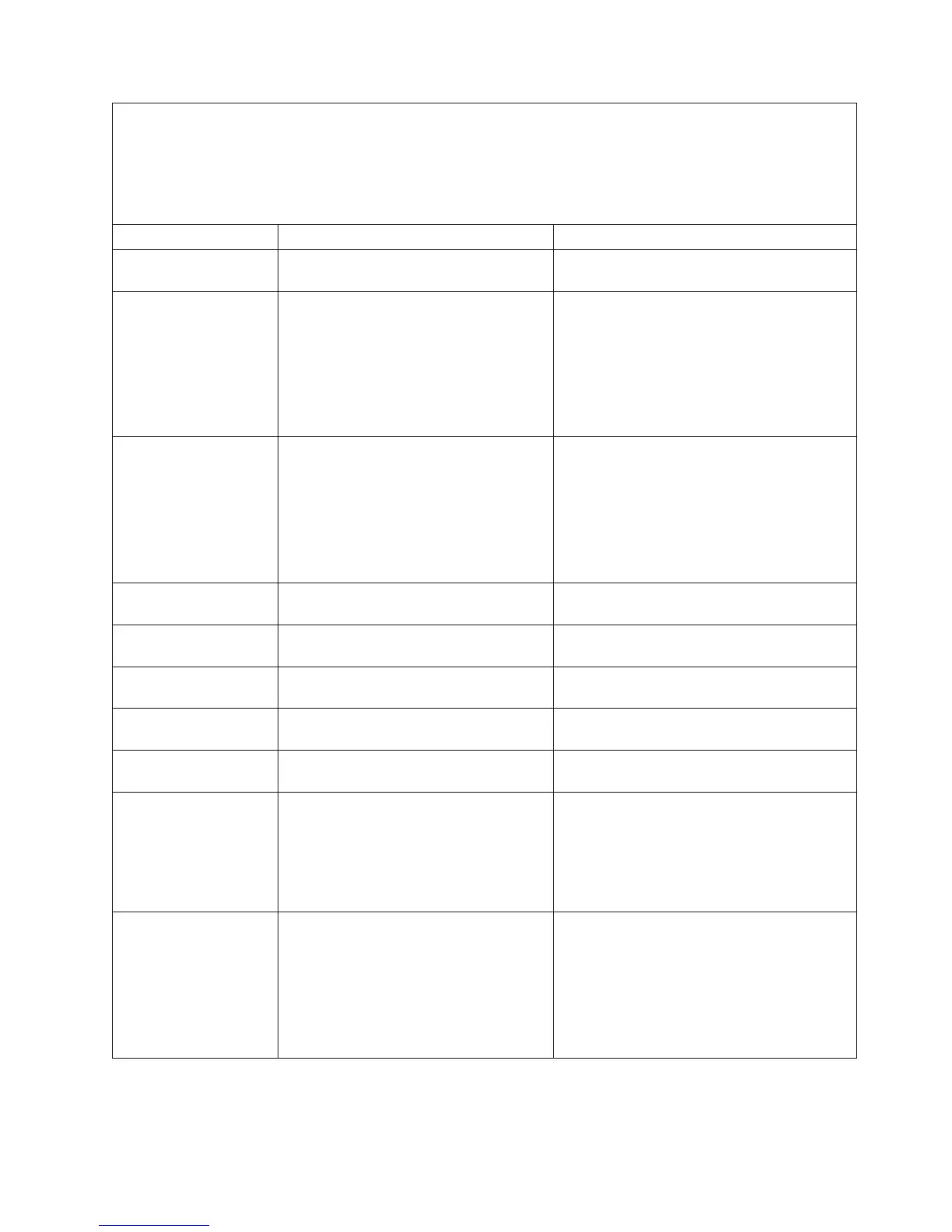
Beep code Description Action
1-2-3 DMA page register write/read failed. (Trained service technician only) Replace the
system board.
1-2-4 RAM refresh verification failed.
1. Reseat the DIMMs.
2. Replace the following components, one at
a time, in the order shown, restarting the
server each time:
a. DIMMs
b. (Trained service technician only)
System board
1-3-1 1st 64K RAM test failed.
1. Reseat the DIMMs.
2. Replace the following components, one at
a time, in the order shown, restarting the
server each time:
a. DIMMs
b. (Trained service technician only)
System board
2-1-1 Secondary DMA register failed. (Trained service technician only) Replace the
system board.
2-1-2 Primary DMA register failed. (Trained service technician only) Replace the
system board.
2-1-3 Primary interrupt mask register failed. (Trained service technician only) Replace the
system board.
2-1-4 Secondary interrupt mask register failed. (Trained service technician only) Replace the
system board.
2-2-1 Interrupt vector loading failed. (Trained service technician only) Replace the
system board.
2-2-2 Keyboard controller failed. Replace the following components, one at a
time, in the order shown, restarting the server
each time:
1. Keyboard
2. (Trained service technician only) System
board
2-2-3 CMOS power failure and checksum
checks failed.
1. Reseat the battery.
2. Replace the following components, one at
a time, in the order shown, restarting the
server each time:
a. Battery
b. (Trained service technician only)
System board
Chapter 2. Diagnostics 19

 Loading...


