The UpdateXpress System Pack Installer
The UpdateXpress System Pack Installer detects supported and installed device
drivers and firmware in the server and installs available updates. For additional
information and to download the UpdateXpress System Pack Installer, go to the
System x and BladeCenter Tools Center at http://publib.boulder.ibm.com/
infocenter/toolsctr/v1r0/index.jsp and click UpdateXpress System Pack Installer.
Server controls, LEDs, and power
This section describes the controls and light-emitting diodes (LEDs) and how to
turn the server on and off.
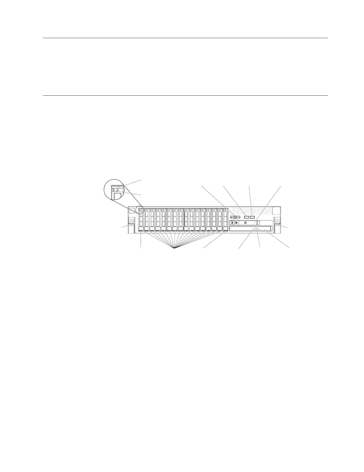
Front view
The following illustration shows the controls, connectors, and hard disk drive bays
on the front of the server.
Hard disk drive activity LED: Each hard disk drive has an activity LED. When
this LED is flashing, it indicates that the drive is in use.
Hard disk drive status LED: Each hard disk drive has a status LED. When this
LED is lit, it indicates that the drive has failed. When this LED is flashing slowly
(one flash per second), it indicates that the drive is being rebuilt as part of a RAID
configuration. When the LED is flashing rapidly (three flashes per second), it
indicates that the controller is identifying the drive.
Video connector: Connect a monitor to this connector. The video connectors on the
front and rear of the server can be used simultaneously.
USB connectors: Connect a USB device, such as USB mouse, keyboard, or other
USB device, to either of these connectors.
Operator information panel: This panel contains controls, light-emitting diodes
(LEDs), and connectors. For information about the controls and LEDs on the
operator information panel, see “Operator information panel” on page 16.
Rack release latches: Press these latches to release the server from the rack.
Hard disk drive
activity LED (green)
Hard disk drive
status LED (amber)
Hard disk
drive bays
Rack
release
latch
Video
connector
USB 1
connector
USB 2
connector
Operator
information panel
CD/DVD
eject button
CD/DVD drive
activity LED
Rack
release
latch
CD/DVD drive
(optical drive)
Bay 15Bay 0
Figure 5. Controls, connectors, and hard disk drive bays front view
Chapter 1. The System x3650 M3 server 15

 Loading...


