12
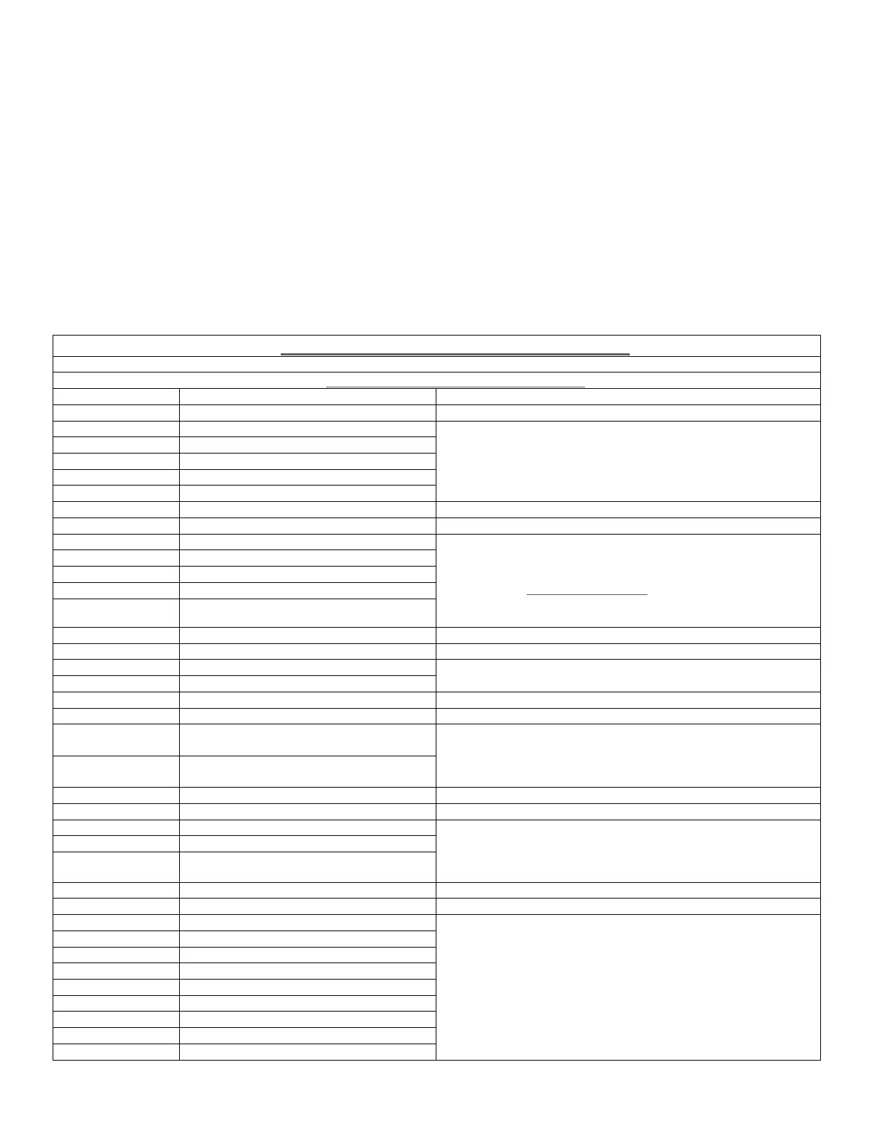
EXTERNAL CONNECTION WIRING TABLE
Connections To / From (i602) I/O Board
CN1 RS232 Communications
2 Receive Data
3 Transmit Data
5 0v Ref
1,4,6,7,8,9 No Connection
Shell Earth – (Screen)
Suitable twisted screened cable up to a maximum distance
of 15 Meters
See Section 6.0 for further details
CN2 DC Supply Connection
1 + 24v DC supply in
2 0 v DC supply in
3 N/C
4 N/C
5 Mains/Batt (See Note 1)
16x0.25 - 15Amp (18 AWG) Cable
(or direct connection from AC PSU Option Module ‘flying
lead’ if fitted)
Note 1: For 24v DC operation
– add a wire link between
pin 2 (0v) and pin 5.
See Section 2.2.4 for further details
CN3 Auxiliary Supply Output
1 Auxiliary 0v DC supply output
2 Auxiliary +24v DC supply output
7x0.2 - 6Amp (24 AWG) Cable
Max Load = 1 Amp
CN4 Remote Reset Connections
1
Remote Reset –Ve - Opto isolated
input
2
Remote Reset +Ve - Opto isolated
input
24v low current signal
CN6 RS 485 Communications
1 Shield
2 RS485 Comms -Ve
3 RS485 Comms +Ve
Belden 9842 cable (or suitable equivalent).
Note : Ensure ‘Mid/End Jumper Link’ fitted correctly on
pins 7/8/9 of CN 5
See Section 4 for further details
CN7 Output Relay Connections
1 Fire 2 - RL 1 Common
2 Fire 2 - RL 1 Normally Closed
3 Fire 2 - RL 1 Normally Open
4 Fire 1 - RL 2 Common
5 Fire 1 - RL 2 Normally Closed
6 Fire 1 - RL 2 Normally Open
7 Action - RL 3 Common
8 Action - RL 3 Normally Closed
9 Action - RL 3 Normally Open
7x0.2 - 6Amp (24 AWG) Cable
Note : Maximum relay contact rating =2 Amp @ 30v DC
See Section 3.5.1 for further details