16
2.2.3 Standby Battery (optional)
This does not apply to the E-Series PICO.
Fit 2 of 12 V sealed lead-acid batteries (17 AH) in series. Locate on the battery shelf, one in front of the other, upright, with the terminals
at the top. The recommended wire for the battery connection cable is: - 18 SWG (15 Amp) cable complying with UL1007. The correct
charging voltage is temperature dependent, and the temperature sensor (supplied) must be connected and taped to one of the batteries. If
batteries are fitted, the internal charger must be enabled. (See the CONFIGURE section; set STANDBY = 1)
ICAM recommend the User/Installer fits either:-
YUASA – Maintenance Free, Re-Chargeable Lead Acid Battery TYPE: NP 18.0-12 or Equivalent, or
YUASA – Maintenance Free, Re-Chargeable Lead Acid Battery TYPE: NP 17.0-12 or Equivalent.
2.2.4 Operation of the FireTracer e-series from 24 Volts DC only
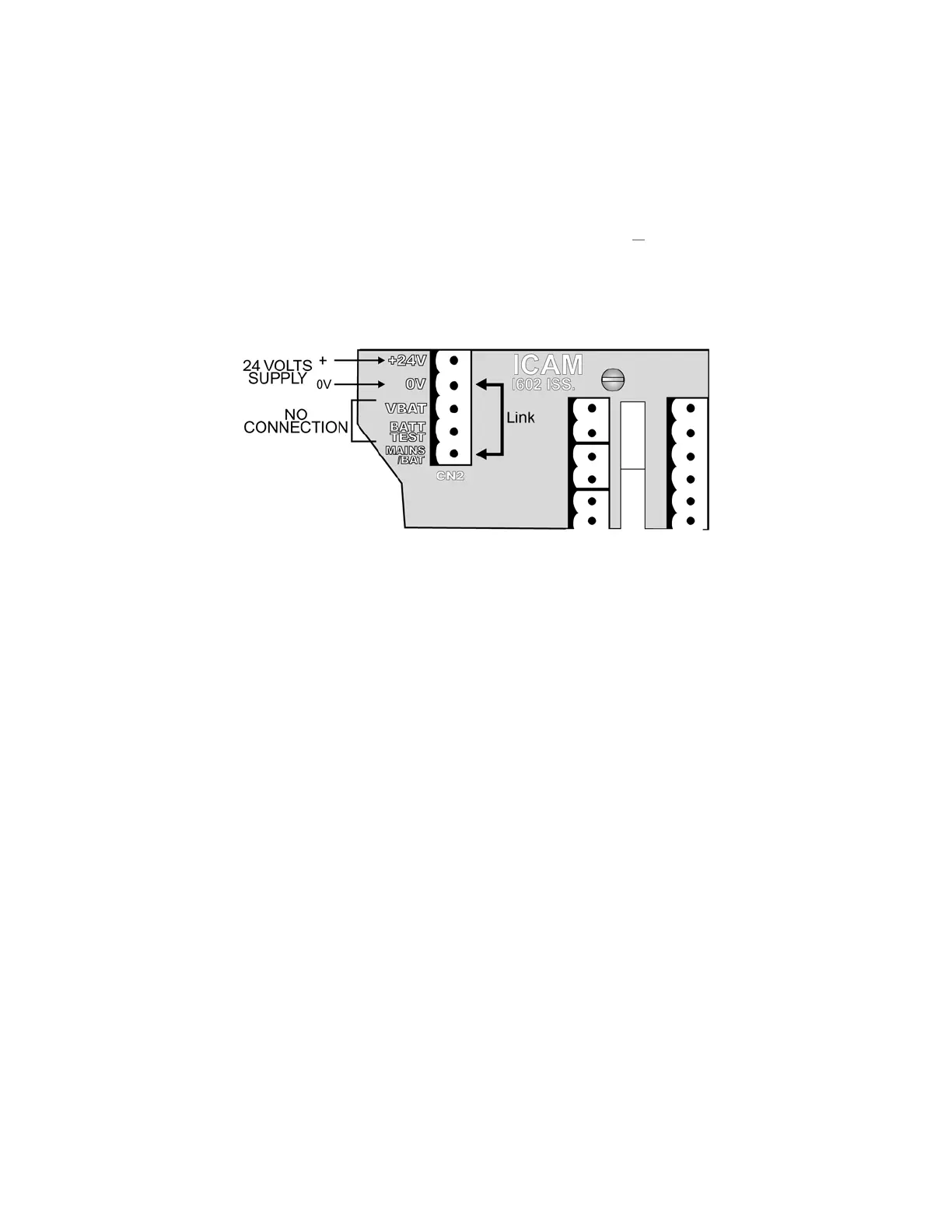
Connect the 24 Volts supply to the 5-way connector (CN2) on the I/O board under the control panel as in the diagram below.
The MAINS/BAT terminal must be linked to 0 V. Failure to do so may result in “MAINS FAULT”. The “VBAT” and “BATT TEST” should be left
unconnected.
Ensure that in the configuration menu, STANDBY = 0.
To reset the e-series, put 24V on to reset input on board.
2.3 Connection of Sampling Tubes
(For more details please refer to the Pipe Installation Manual)
Pico and FT1 sample tubes are 25mm OD UPVC. The inlets are tapered push-fit and pipes should NEVER be glued in place. The
recommended maximum length is 100m per pipe.
FT4 and FT6 sample pipes are 21.4mm OD (1/2” BSP). The inlets are tapered push-fit. For 3/4” BSP pipe system, tapered adaptors maybe
used that should be glued to the pipes. Glue should NEVER be used at the point of entry into the unit. The recommended maximum length
is 100m per pipe.
The FT8 and FT15 sample pipes are 6mm OD / 4mm ID nylon flexible tube. For corrosive conditions, FEB tube may be used. Pipe lengths
should be equal, the recommended maximum being 50m per pipe.
Note: Do not insert ANY object into the ‘Inlet Ports’ other than the correct size of piping. This is to avoid damage to delicate electronic
components mounted just inside each port opening.
Note: As stated above, pipes must NEVER be glued to the unit inlets but the pipe network itself MUST be glued together. Use removable
unions where necessary.