11
2.2.2 PICO Connections
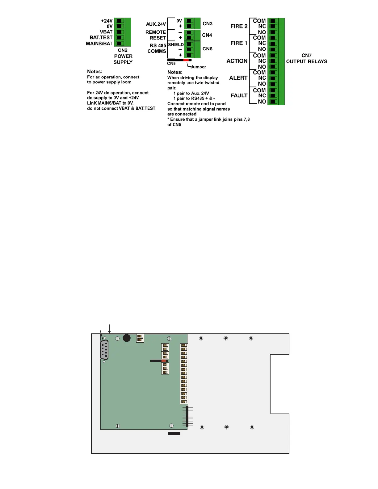
PICO units are powered by an External 24 V DC Supply
Access to the interior of the PICO unit is gained by removal of the front cover. This is secured by four screw lock fixings (one at each of the
four corners), releasing these fixings allows the removal of the cover complete with the ‘self-retained’ fixings.
The Fault Relay and other I/O Module connections are all located on the (i602) printed circuit board immediately on the front face of the
internal metal sub-chassis.
The DC Supply fuse (FS3), which is a 2 Amp Time Delay, is also located on the (i602) printed circuit board.
A cable entry gland is provided on the rear of the bottom casing for entry of the DC Supply Cabling and the field wiring cables. A second
cable entry hole is provided, fitted with 0.2-2mm grommet, to facilitate the Ethernet cable (if used).
The ‘Connection Table’ on pages 12 and 13 provides detailed connection information for:
• The 24 V DC supply
• Fault Relay contact connections
• Auxiliary 24 V output supply (fused to 1 A) for powering an external sounder, addressable I/O units etc.
• Remote Reset input line; Activated by applying 24 V.
• RS485 Communications; Used for operating the Unit remotely, or for ICAMnet where multiple units can be connected to a
host PC running WinTracer or other software.
• Ethernet connection – Used for connecting to a host computer. The Unit can be monitored and driven remotely. The unit
has TCP/IP stack and can generate html pages for viewing on any Web browser.
• RS232 connection – Used for conducting Test/Configuration functions and interrogation of the ‘Fault Log Data’ when
connected to a Remote User Panel or a PC running ICAM Detmon program
Optional plug-on
I/O boards
CN2
1
CN5
Fuse 1A
CN3
CN4
CN6
CN7
I/O Board
OUTPUT RELAY CONTACTS
ICAM
i602
Ethernet
RS232
Programming
Connector
CN1