7
2 INSTALLATION
The units should be installed in accordance with the following installation instructions and in a manner acceptable to the local inspection
authority having jurisdiction. The units are also intended to be installed in accordance with NFPA No. 72 Standard - titled “National Fire
Alarm Code”.
Careful consideration should be given to the mounting location of the FireTracer unit to ensure that:
• It is positioned at an accessible height to facilitate commissioning, routine testing and maintenance.
• It is positioned in an area where the exhaust air pipe will remain clear of obstacles at all times.
• It is not installed above a heat source such as a radiator or in direct air flow source such as Air Conditioners.
• It will be secure and free from operation by unauthorised personnel.
The following steps should be carried out in order to correctly install the FireTracer system.
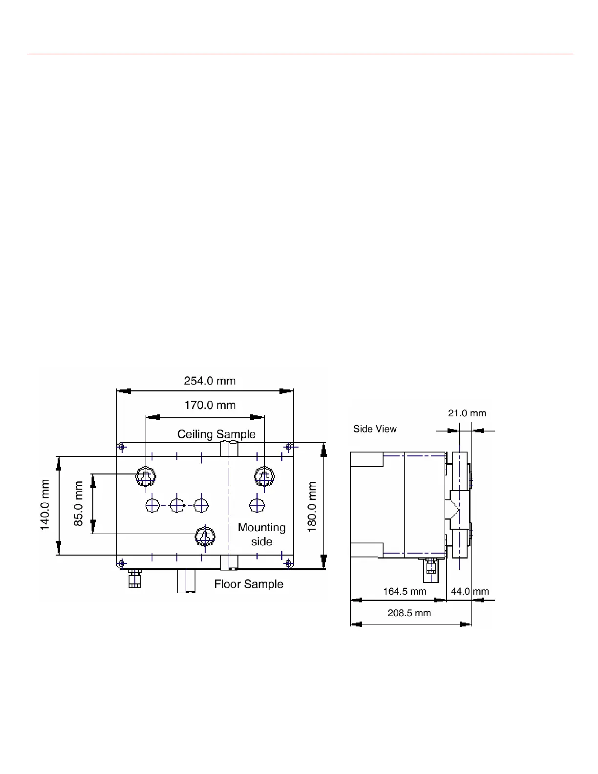
• The FireTracer back box should be securely fitted to a suitable wall or support using the three points shown in the fixing diagrams
in section 2.1. M6 or M8 screws are suitable.
• The cables for the power supply, battery and any I/O modules should be fitted.
• The pipe network is fitted to the system. For details on how to design and install a pipe network, see Pipe Installation Manual
(ICAM Part No. 09-0003-10)
2.1 Mounting Diagrams
Pico Fixin
s