15
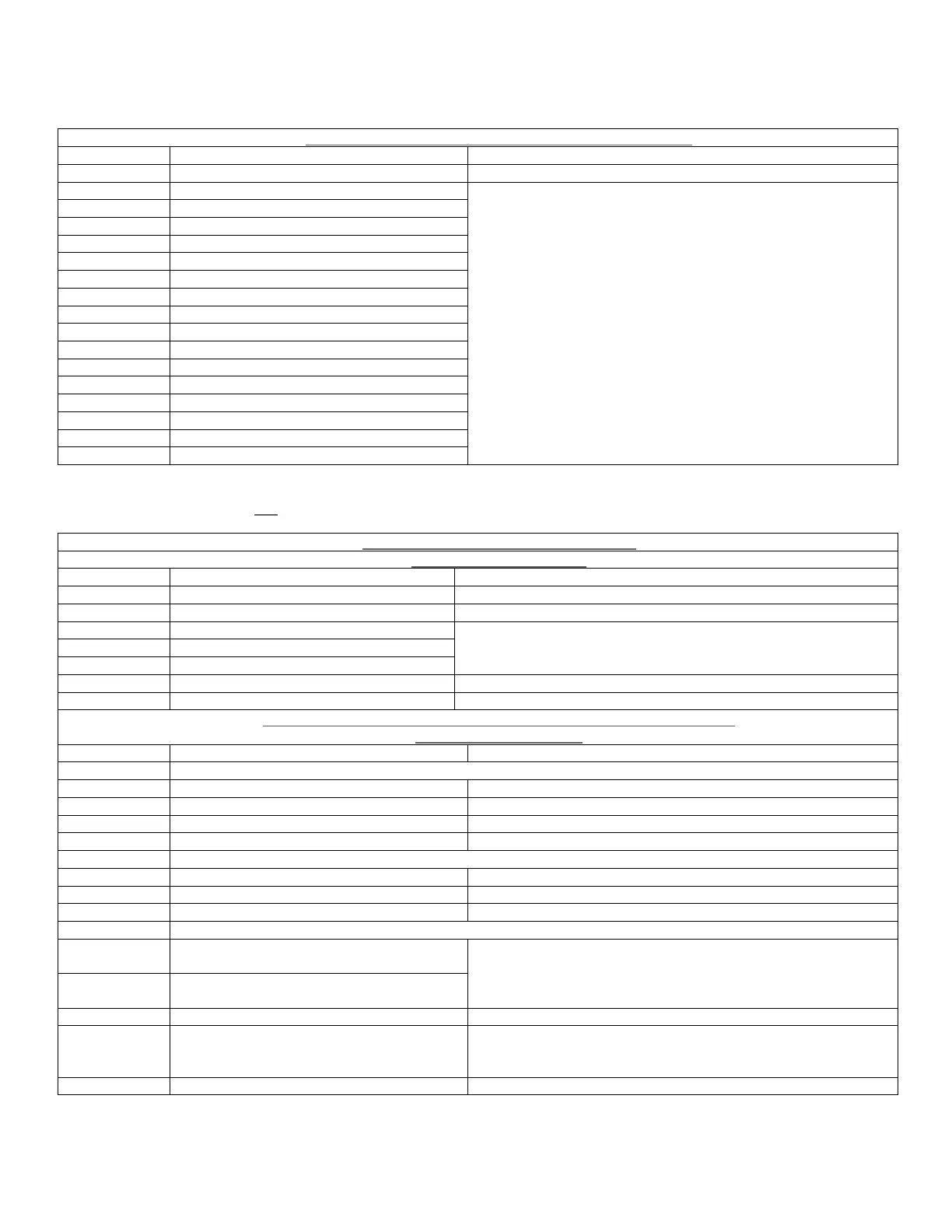
Connections To Analogue Input Board (Option Module)
CN2 Input Connections (i625)
1 Input 1 +ve
2 Input 2 +ve
3 Input 3 +ve
4 Input 4 +ve
5 Input 5 +ve
6 Input 6 +ve
7 Input 7 +ve
8 Input 8 +ve
9 0 v (inputs 1 – 8)
10 0 v (inputs 1 – 8)
11 Input 9 +ve
12 Input 10 +ve
13 Input 11 +ve
14 Input 12 +ve
15 0 v (inputs 1 – 8)
16 +24v
Inputs 1- 8 = Low Level Inputs
(As the gain of these Low Level Inputs is build selectable,
they can on mass be configured as either High Voltage
Inputs or 4 – 20mA Current Inputs)
Inputs 9 - 12 = 4 – 20mA Current Inputs
(Input Z = 100 ohms)
All connections = 7x0.2 - 6Amp (24 AWG) Cable
See Section 3.5.3 for full operational details
The following tables do not apply to the E-Series PICO
Connections To Remote Panel (Option)
From I620 Control Board
CN 2 RS485 Remote Control Data
1 +24v DC – Supply out Belden 9842 cable (or equivalent) – 24 AWG
2 0v - Supply Common
3 RS485 +ve - Data
4 RS485 -ve - Data
Note: Ensure ‘Mid/End Jumper Link’ fitted to the ‘End’ position
(pins 1&2 of CN 6).
See sections 2.6, 2.7 & 4.0 for further details
Connections To / From Mains PSU/Battery Charge (Option Module)
110v and 230v versions
CN1 A/C Supply Connector (i601 Board)
1 Live 16x0.25 - 15Amp (18 AWG) Cable
2 Neutral
3 Earth
CN1 Back-Up Battery Connector (i614 Board)
1 0v - To Negative battery terminal 26x0.25 - 19Amp (16 AWG) Cable
2 +24v - To Positive battery terminal See section 2.2.1 for further details
CN8 Battery Thermistor Connection (i614 Board)
1
Battery Thermistor (not polarity
conscious)
2
Battery Thermistor (not polarity
conscious)
Note : The ‘Battery Thermistor’ must be connected when a
Back-up Battery is connected
5 pin flying
Lead
Connector
Mains PSU DC Output Connection
(from i614 Board)
Connects to CN 2 on i602 Board