17
1
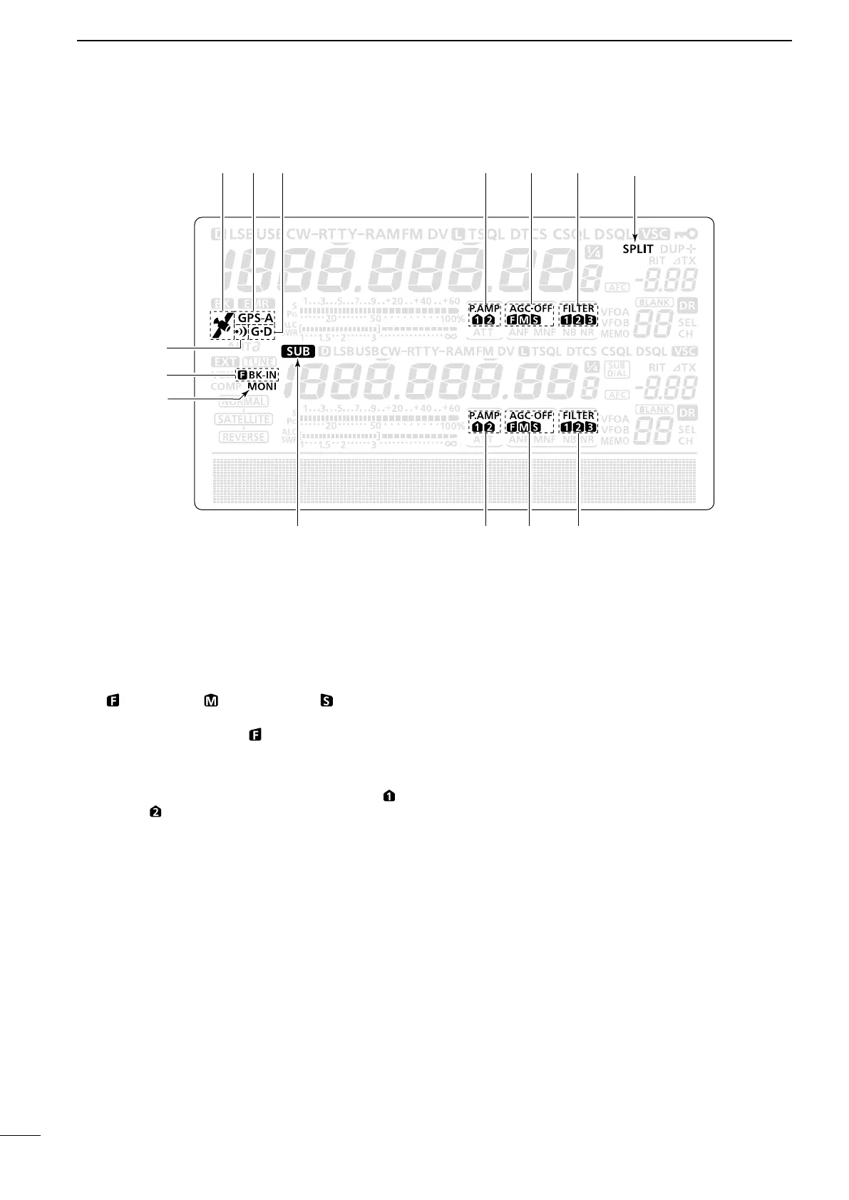
PANEL DESCRIPTION
■ LCD display (Continued)
@1 SPLIT ICON (p. 82)
Appears when the Split function is turned ON.
@2 DSP FILTER ICON (p. 73)
Displays the selected IF filter.
@3 AGC ICONS (p. 72)
Displays the selected AGC time constant.
•“ ”forAGCfast;“ ”forAGCmiddle;“ ”forAGCslow;
“-OFF” for AGC OFF.
•IntheFMandDVmode,“
” for AGC fast is fixed.
@4 PREAMP ICON (p. 71)
Appears when a preamplifier is turned ON.
•In HF/50 MHzfrequency band, either“P.AMP ” or
“P. AMP
” is displayed when the preamp 1 or preamp 2
is ON.
@5 GPS DATA COMMUNICATION ICON
Appears while the GPS data communication func-
tion is selected in the “GPS Out” item of the Set
mode. (p. 168).
•AGPSdatafromtheGPSreceiver,whichisconnected
to the [DATA1] jack, is output to the [USB] port.
@6 GPS TX ICON (p. 134)
➥“GPS” appears when the GPS transmission
mode is set to GPS.
➥“GPS-A” appears when GPS transmission mode
is set to GPS-A.
@7 GPS ICON (p. 132)
➥ Appears when a valid position data is received
from a GPS receiver that is connected to the
[DATA1] jack.
➥Blinks when an invalid data is received from the
GPS receiver.
@8 GPS ALARM ICON (p. 130)
Appears when the GPS alarm function is turned
ON.
@9 BREAK-IN ICON (p. 79)
➥“
F
BK-IN” appears when the Full Break-in func-
tion is turned ON.
➥“BK-IN” appears when the Semi Break-in func-
tion is turned ON.
#0 MONITOR ICON (p. 81)
Appears when the Monitor function is turned ON.
#1 SUB ICON (p. 33)
Appears when the SUB Band setting mode is ON.
 Loading...