3
1
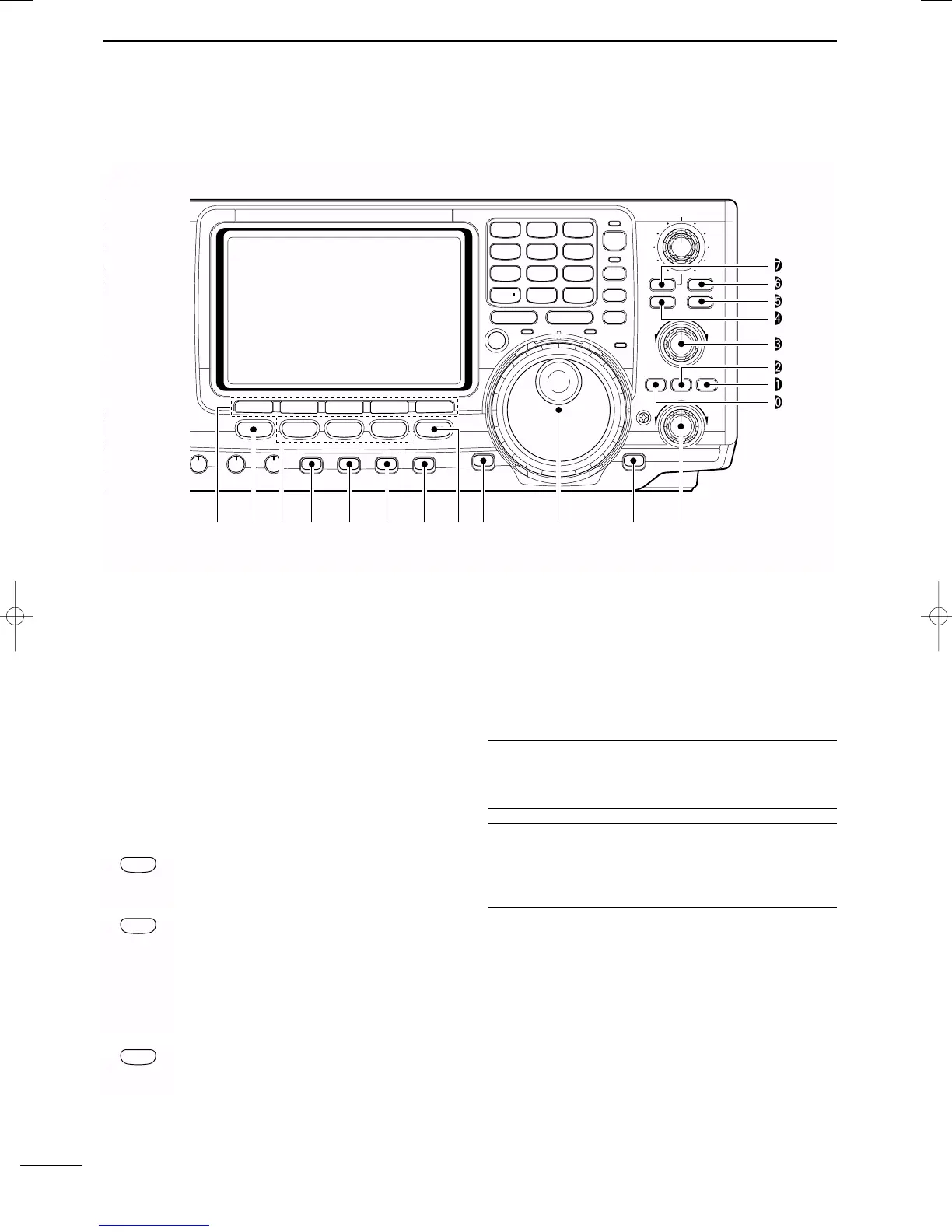
PANEL DESCRIPTION
2001 NEW 2001 NEW
■ Front panel (continued)
!8 MULTI-FUNCTION SWITCHES [F1]–[F5]
➥Push to select the function indicated in the LCD
display above these switches. (p. 11)
•Functions vary depending on the operating mode.
➥Push to input a character for memory keyer pro-
gramming or memory name. (pgs. 31, 66)
!9 MENU SWITCH [MENU]
Push to change the set of functions assigned to the
multi-function switches.
• Toggles between menu 1 (M1) and menu 2 (M2).
@0 MODE SWITCHES
Selects the desired mode. (p. 23)
•Announces the selected mode when an optional UT-102
is installed. (p. 89)
➥ Selects USB and LSB mode alternately.
➥ Selects SSB data mode (USB-D, LSB-D)
when pushed for 1 sec. in SSB mode.
➥ Selects CW and RTTY mode alternately.
➥ Switches CW and CW-R (CW reverse)
mode when pushed for 1 sec. in CW
mode.
➥ Switches RTTY and RTTY-R (RTTY re-
verse)
mode when pushed for 1 sec. in
RTTY mode.
➥ Selects AM and FM mode alternately.
➥ Selects AM/FM data mode (AM-D, FM-D)
when pushed for 1 sec. in AM/FM mode.
@1 PREAMP/ATTENUATOR SWITCH [P.AMP/ATT]
(p. 47)
➥ Push momentarily to toggle between preamp-1
and preamp-2.
•“P.AMP1” activates for HF all bands.
•“P.AMP2” activates high-gain preamp for 24 MHz
band and above.
➥ Push for 1 sec. to toggle the attenuator function
ON and OFF.
✔
What is the preamp?
The preamp amplifies received signals in the front end cir-
cuit to improve the S/N ratio and sensitivity. Select “P.AMP1”
or “P.AMP2” when receiving weak signals.
✔
What is the attenuator?
The attenuator prevents a desired signal from distorting
when very strong signals are near the desired frequency, or
when very strong electric fields, such as from a broadcast-
ing station, are near your location.
@2 NOISE BLANKER SWITCH [NB] (p. 50)
➥ Switches the noise blanker ON and OFF when
pushed. The noise blanker reduces pulse-type
noise such as that generated by automobile igni-
tion systems. This function cannot be used for
FM, or non-pulse-type noise.
•“NB” appears while the noise blanker is activated.
➥ Enters the noise blanker level set mode when
pushed for 1 sec.
T
Y
NR
A
/NOTCH
TUNER
ANT
HF/VHF TRANSCEIVER
NR
NOTCH
AF
MIC GAIN
RF PWR
CW PITCH
F 1
F
2F
3
F
4
F
5
XFC
MP
-
W
GENE
50
0
21
7
24
8
28
9
14
5
10
4
18
6
3.5
2
1. 8
1
7
3
144
ENT
MP
-
R
TX
RX
LOCK
TWIN PBT
M-CH
RIT
CLEAR
∂TX
RIT/∂TX
TS
SPLIT
PBTC
F-INP
A/B
V/M
MW
M-CL
KEY SPEED
P.AMP/ATT
NB
VOX/BK-IN
MONITOR
CALL
LOCK/
SPCH
RF/SQL
i746PRO
MENU
SSB
CW/RTTY
AM/FM
FILTER
#7
#6
#5
#4
#3
#2
#1
#0
!9 @0 @1!8 @2 @3 @4
@6@5 @7 @8 @9
IC-7400.qxd 02.4.2 11:35 Page 3