EasyManua.ls Logo

Icom IC-M424 - User Manual

Icom IC-M424
108 pages
Print Icon
To Next Page IconTo Next Page
Loading...
INSTRUCTION MANUAL
iM423
VHF MARINE TRANSCEIVER
iM424
This device complies with Part 15 of the FCC
Rules. Operation is subject to the condition that
this device does not cause harmful interference.

Table of Contents

Other manuals for Icom IC-M424

Questions and Answers

  • H
    hailey57Sep 2, 2025
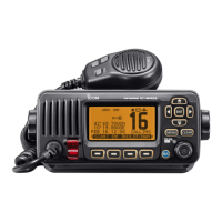
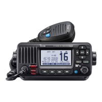
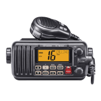
    How to fix Icom IC-M424 Transceiver that does not turn ON?
    • A
      Amy WalkerSep 2, 2025
      If your Icom Transceiver won't turn on, the most likely cause is a bad connection to the power source. Check the connection to both the transceiver and the power source to ensure they are properly connected.
  • C
    Chelsea WilsonAug 31, 2025
    Why is there no sound coming from my Icom IC-M424 speaker?
    • K
      Kurt EstesAug 31, 2025
      If you're experiencing little to no sound from the speaker of your Icom Transceiver, there could be a few reasons. First, the squelch level might be set too high; try setting the squelch to the threshold point. Second, the volume level could be too low; adjust the volume to a suitable level. Finally, if the speaker has been exposed to water, use the AquaQuake function to remove it.
  • R
    Ryan FernandezAug 29, 2025
    How to enable beep sounds on Icom IC-M424?
    • T
      Tina OwensAug 29, 2025
      If there are no beep sounds on your Icom Transceiver, the beep tones are likely turned OFF. To resolve this, turn ON the beep tones in the CONFIGURATION menu.
  • M
    Michael MerrittAug 27, 2025
    What to do if Icom IC-M424 Transceiver displays 'NO POSITION' and 'NO TIME'?
    • A
      Alexander KelleyAug 28, 2025
      If “NO POSITION” and “NO TIME” are displayed on your Icom Transceiver instead of the actual position and time, this indicates that the GPS signal is not being received correctly. Try mounting the transceiver in a location where no objects obstruct the satellite signal. Alternatively, the position and time may not have been manually entered; in this case, enter the position and time manually.
  • R
    robertjohnsonAug 26, 2025
    Why Icom Transceiver scan does not start?
    • H
      Heidi MarquezAug 27, 2025
      If your Icom Transceiver scan does not start, it could be because no favorite channels have been entered. Set the desired channels as favorite channels to enable the scan function.
  • B
    Bryan AcostaAug 25, 2025
    What to do if distress calls cannot be transmitted on Icom IC-M424 Transceiver?
    • M
      Ms. Breanna BoydAug 25, 2025
      If distress calls cannot be transmitted on your Icom Transceiver, it is likely because the MMSI (DSC self ID) code has not been entered. Enter the MMSI (DSC self ID) code to resolve this issue.
  • B
    brucejonesAug 22, 2025
    Why Icom Transceiver transmitting is impossible?
    • R
      Robert LeblancAug 22, 2025
      If you cannot transmit or select high power on your Icom Transceiver, it may be due to the following reasons: 1. Some channels might be restricted to low power or receive-only due to regulations. Try changing to a different channel. 2. The output power may be set to low. Push the [HI/LO] button to select high power.

Summary

FOREWORD

EXPLICIT DEFINITIONS

Defines terms used in the manual, including warnings and notes.

IN CASE OF EMERGENCY

Using Channel 16 for Distress Calls

Procedure for distress calls using Channel 16.

Using Digital Selective Calling (Ch 70)

Procedure for distress calls using Digital Selective Calling.

RADIO OPERATOR WARNING

FCC INFORMATION

NOTE

PRECAUTIONS

1 OPERATING RULES

2 PANEL DESCRIPTION

Front panel

Describes the front panel layout and controls of the transceiver.

Function display

Explains the icons and information shown on the transceiver's display.

Speaker Microphone

Details the speaker microphone functions and connections.

Softkey function

Explains how softkey functions are assigned and used.

3 PREPARATION

MMSI code programming

Guide to programming the Maritime Mobile Service Identity (MMSI) code.

4 BASIC OPERATION

Channel selection

How to select operating channels, including Channel 16 and Call channels.

Receiving and transmitting

Instructions for receiving signals and transmitting messages.

Call channel programming

How to program a specific Call channel for quick recall.

Channel name programming

How to assign a name to a specific channel.

Microphone Lock function

How to enable or disable the microphone lock function.

Adjusting the volume level

How to adjust the audio volume level of the transceiver.

Adjusting the squelch level

How to adjust the squelch level for optimal signal reception.

Adjusting the display backlight level

How to adjust the brightness of the LCD and key backlight.

AquaQuake water draining function

Function to clear water from the speaker grill.

5 SCAN OPERATION

Scan types

Explains Priority and Normal scan modes for efficient signal locating.

Setting Favorite channels

How to add or clear channels for efficient scanning.

Starting a scan

Steps to initiate Priority or Normal scans.

6 DUALWATCH;TRI-WATCH

Description

Explains Dualwatch and Tri-watch for monitoring Channel 16 and Call channel.

Operation

How to select and start Dualwatch or Tri-watch modes.

7 DSC OPERATION

DSC address ID

How to program and manage individual and group DSC address IDs.

Programming Group ID

Procedure for programming Group IDs for DSC calls.

Deleting Individual;Group ID

Steps to delete programmed Individual or Group DSC IDs.

Position and time programming

Manually inputting ship's position and UTC time for distress calls.

Distress call

Procedure for transmitting distress calls via DSC.

Transmitting DSC calls

How to send various types of DSC calls to specific stations.

Receiving DSC calls

Procedures for receiving and responding to DSC calls.

Received Call log

Accessing and managing stored received DSC messages.

Transmitted Call log

Accessing and managing stored transmitted DSC calls.

DSC Settings

Configuring various DSC operational parameters and functions.

Channel 16 Switch function

Setting how the transceiver handles Channel 16 after a distress call.

DSC Data Output

Configuring DSC data output to connected devices.

Alarm

Setting alarm functions for different DSC categories or statuses.

Channel 70 Squelch level

Adjusting the squelch level for Channel 70.

DSC Loop Test

Performing a loop test to check DSC transmit and receive circuits.

Making an Individual call using an AIS transponder

Transmitting DSC calls to AIS targets via the transponder.

8 OTHER FUNCTIONS

Intercom operation

How to use the intercom function with the optional microphone.

RX Speaker function

How to output received audio to an external PA speaker.

PA (Public Address) function

How to use the PA function for announcements through a PA speaker.

Horn function

How to activate the horn function.

9 MENU SCREEN OPERATION

Menu screen operation

Overview of using the menu screen for settings and calls.

Entering the Menu screen and operation

Step-by-step guide to navigating and operating the menu screen.

Menu screen items

Lists all available items and their page references within the menu system.

Individual Call

Details on initiating and managing individual DSC calls.

Position Input

Configuration for GPS position input in DSC settings.

Scan Type

Selection of Normal scan or Priority scan modes.

Backlight

Adjustment of the LCD and key backlight brightness.

MMSI;GPS Information

Displays programmed MMSI code and GPS information.

Scan resume timer

Setting scan pause behavior for Normal and Priority scans.

Dual;Tri-watch

Option to select Dualwatch or Tri-watch monitoring modes.

Channel Group

Selection of appropriate channel groups (USA, INT, CAN).

Weather alert

Setting up weather alert tones and scanning of weather channels.

Key Assignment

Assigning functions to Dial and softkeys for customized operation.

Softkeys assignment

Assigning functions to softkey buttons for quick access.

UTC Offset

Setting the local time offset from UTC.

Noise Cancel

Adjusting noise reduction for receive and transmit signals.

Inactivity Timer

Setting automatic return to normal screen after periods of inactivity.

Remote ID

Setting a Remote ID number for NMEA format.

COMMANDMIC Speaker

Selecting internal or external speaker for the COMMANDMIC.

10 CONNECTIONS AND MAINTENANCE

Connections

Diagrams and descriptions of all transceiver connection ports.

DC POWER CONNECTOR

Connecting the transceiver to a 13.8 V DC power source.

GROUND TERMINAL

Connecting to a vessel ground for safety and interference reduction.

COMMAND MICROPHONE JACK

Jack for connecting the optional Command microphone.

Connect to the MA-500 TR

Connecting the transceiver to the MA-500TR AIS transponder.

Antenna

Importance of antenna selection and mounting for performance.

Fuse replacement

Procedure for replacing a blown fuse in the DC power cable.

Cleaning

How to clean the transceiver using a soft, dry cloth.

Supplied accessories

List of items included in the transceiver package.

Mounting the transceiver

Instructions for mounting the transceiver using the supplied bracket.

MB-132 installation

Guide for flush mounting the transceiver using the MB-132 kit.

Microphone installation

Instructions for installing the HM-195 Command microphone and its cable.

11 SPECIFICATIONS AND OPTIONS

Specifications

Technical details of the transceiver's general, transmitter, and receiver performance.

Options

List and description of optional accessories available for the transceiver.

12 CHANNEL LIST

13 TROUBLESHOOTING

14 TEMPLATE

Icom IC-M424 Specifications

General IconGeneral
TypeMarine VHF Transceiver
Frequency Range156.000 - 163.425 MHz
Waterproof RatingIPX7
DisplayLCD
GPSNo
DSCYes
Power Supply13.8 V DC
ModulationFM
Current Consumption1.5 A (max)
Output Power25W

Related product manuals