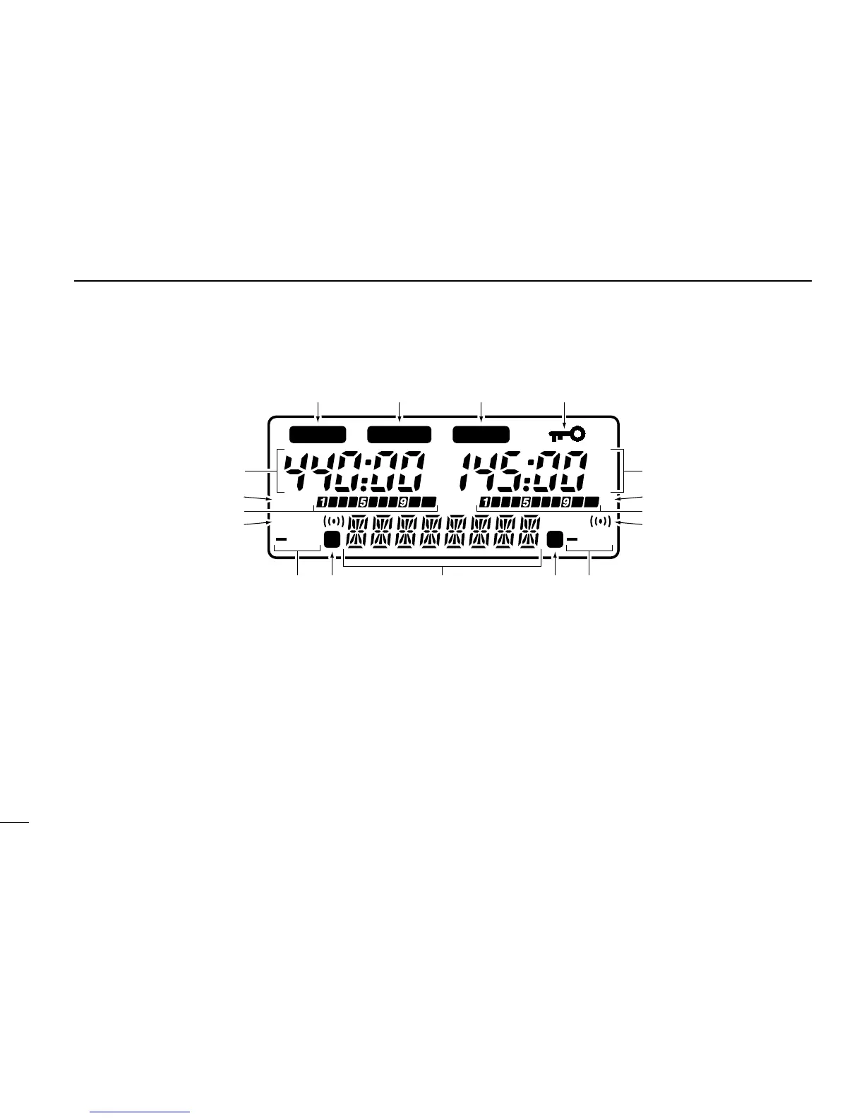
EasyManuals Logo

Icom IC-W32A User Manual

Icom IC-W32A
49 pages
To Next Page IconTo Next Page
To Previous Page IconTo Previous Page
Page #10 background imageLoading...
Page #10 background image
1
PANEL DESCRIPTION
6
LOW
TSQL
DUP
MAIN MAIN
S
GUIDE
75
50
25
LOW
75
50
25
TSQL
DUP
S
qq
w
e
t
r
w
uui
o!0
y
e
t
r
y
Function display
q MAIN BAND INDICATORS (p. 13)
Appear above the frequency which is selected as the main
band.
Only one of these indicators appears at a time.
w FREQUENCY READOUTS
Show the operating frequency, set mode contents, etc.
The frequency on the left and right can be exchanged. (p. 13)
The smaller 75, 50 and 25 to the right of each readout indi-
cate 7.5, 5.0 and 2.5 kHz, respectively.
The decimal point of the frequency ashes during scan. (p. 29)
While operating in the avionics band, a colon appears to indicate
AM mode. (U.S.A. and Asia versions only)

Table of Contents

Questions and Answers:

Question and Answer IconNeed help?

Do you have a question about the Icom IC-W32A and is the answer not in the manual?

Icom IC-W32A Specifications

General IconGeneral
BrandIcom
ModelIC-W32A
CategoryTransceiver
LanguageEnglish

Related product manuals