S
MART
AXIS P
RO
/L
ITE
U
SER
'
S
M
ANUAL
FT9Y-B1378 5-33
5: S
PECIAL
F
UNCTIONS
2. Select Catch Input in the Groups 1 through 4 pull-down list boxes. The Catch Input dialog box appears.
3. Select Catch Input Rising Edge or Catch Input Falling Edge in the pull-down list.
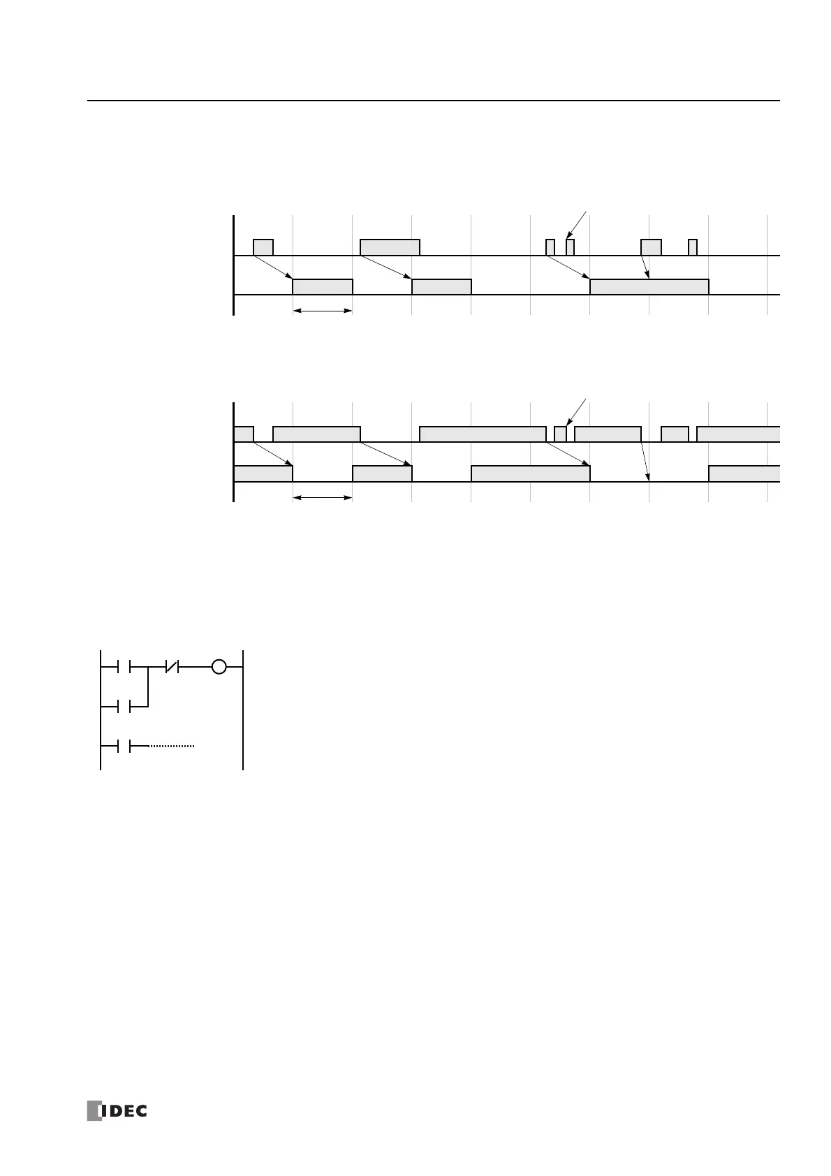
Catching Rising Edge of Input Pulse
Catching Falling Edge of Input Pulse
Note: When two or more pulses enter within one scan, subsequent pulses are ignored.
Example: Maintaining Catch Input
When a catch input is received, the catch input relay assigned to a catch input is turned on for only one scan. This example
demonstrates a program to maintain a catch input status for more than one scan.
Actual Input
ON
OFF
Catch Input Relay
ON
OFF
(M8090-M8095)
Note
END
Processed
1 scan time
Actual Input
ON
OFF
Catch Input Relay
ON
OFF
(M8090-M8095)
Note
END
Processed
1 scan time
Input I2 is designated as a catch input using the Function Area Settings.
When input I2 is turned on, special internal relay M8091 is turned on, and M0 is maintained in the self-
holding circuit.
When NC input M1 is turned off, the self-holding circuit is unlatched, and M0 is turned off.
M0 is used as an input condition for the subsequent program instructions.