EasyManua.ls Logo

IDEC FT1A Series User Manual

IDEC FT1A Series
393 pages
To Next Page IconTo Next Page
To Previous Page IconTo Previous Page
Page #123 background imageLoading...
Page #123 background image
S
MART
AXIS P
RO
/L
ITE
U
SER
'
S
M
ANUAL
FT9Y-B1378 5-35
5: S
PECIAL
F
UNCTIONS
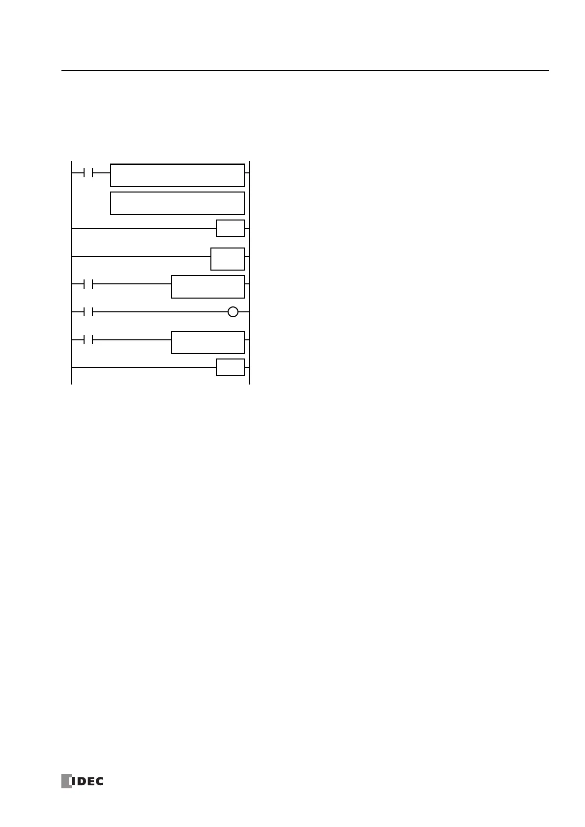
Example: Interrupt Input
The following example demonstrates a program using the interrupt input function, with input I2 designated as an interrupt input.
When the interrupt input is turned on, the input I0 status is immediately transferred to output Q0 using the IOREF (I/O refresh)
instruction before the END instruction is executed. For the IOREF instruction, See Chapter 15 "Refresh Instructions" in the
"SmartAXIS Ladder Programming Manual".
Notes for Using Interrupt Inputs and Timer Interrupt:
• When using an interrupt input or timer interrupt, separate the interrupt program from the main program using the END instruction at the end
of the main program.
• When an interrupt program calls another subroutine, a maximum of 3 subroutine calls can be nested. If more than 3 calls are nested, a user
program execution error occurs, turning on special internal relay M8004 and the ERR LED.
• When using an interrupt input or timer interrupt, include the label number of the interrupt program to be executed when an interrupt occurs.
The label numbers stored in data registers D8032 through D8035, D8037, and D8038 specify the interrupt programs for interrupt inputs I0,
I2, I3, and I5 through I7 and timer interrupt, respectively.
• When more than one interrupt input is turned on at the same time, interrupt program execution is given priority to inputs I0, I2, I3, I5, I6,
and I7, in that order. If an interrupt is initiated while another interrupt program is executed, the subsequent interrupt program is executed
after the prior interrupt is completed. Multiple interrupt programs cannot be executed simultaneously.
• Make sure that the execution time of the interrupt program is shorter than interrupt intervals sufficiently.
• Interrupt programs cannot use the following instructions: SOTU, SOTD, TML, TIM, TMH, TMS, TMLO, TIMO, TMHO, TMSO, CNT, CDP, CUD,
CNTD, CDPD, CUDD, SFR, SFRN, WEEK, YEAR, MSG, DI, EI, XYFS, CVXTY, CVYTX, AVRG, PULS, PWM, RAMP, ZRN, ARAMP, DTML, DTIM,
DTMH, DTMS, TTIM, FIFOF, NDSRC, HOUR, TXD, RXD, ETXD, ERXD, DLOG, and TRACE.
LABEL
0
M8120
END
Main Program
M8125
Q0
REPS1 –
0
D1 –
D8033
MOV(W)
IOREF S1
I0
M300
M8125
IOREF S1
Q0
LRET
M8120 is the initialize pulse special internal relay.
D8033 stores 0 to designate jump destination label 0 for interrupt input I2.
The interrupt program is separated from the main program by the END instruction.
When input I2 is on, program execution jumps to label 0.
M8125 is the in-operation output special internal relay.
IOREF immediately reads input I0 status to internal relay M300.
M300 turns on or off the output Q0 internal memory.
Another IOREF immediately writes the output Q0 internal memory status to actual
output Q0.
Program execution returns to the main program.
Insert LRET at the end of the subroutine to return to the main program.

Table of Contents

Question and Answer IconNeed help?

Do you have a question about the IDEC FT1A Series and is the answer not in the manual?

IDEC FT1A Series Specifications

General IconGeneral
Programming SoftwareWindLDR
TypeProgrammable Logic Controller (PLC)
DisplayLCD (varies by model)
Communication PortsRS232C/RS485 (built-in), USB (programming), Ethernet (optional)
DimensionsVaries by model
WeightVaries by model
ModelFT1A Series

Summary

SAFETY PRECAUTIONS

Warning Notices

Emphasizes potential severe personal injury or death from improper operation.

Caution Notices

Highlights risks of personal injury or equipment damage from inattention.

ABOUT THIS MANUAL

Introduction

Overview of the manual's content and scope regarding SmartAXIS.

Regarding laws and compatible standards

Details compliance with European, North American, and Marine standards.

GENERAL INFORMATION

About the SmartAXIS

Describes the SmartAXIS as a compact programmable controller with powerful functions.

Features

Highlights key features like high-speed counters, HMI, and communication capabilities.

Special Functions

Covers advanced features like Catch Input, Interrupt Input, and High-speed Counter.

Communication Functions

Details the various communication capabilities via USB, Ethernet, and expansion ports.

PRODUCT SPECIFICATIONS

Parts Description

Identifies and describes the physical components of SmartAXIS Pro and Lite models.

Input Specifications (AC Power Type)

Provides detailed electrical specifications for AC power type inputs.

SD Memory Card

Explains SD card usage, specifications, and file system details for data logging.

Communication Cartridge

Details the functions and specifications of communication cartridges like RS232C and RS485.

Memory Cartridge

Explains the function and specifications of the memory cartridge for user program storage.

INSTALLATION AND WIRING

Installation Location

Specifies suitable and unsuitable environments for SmartAXIS installation.

Input/Output Wiring

Details wiring procedures and precautions for connecting input and output devices.

Power Supply

Explains how to connect AC and DC power supplies, including inrush current.

OPERATION BASICS

Start WindLDR

Guides on launching and starting the WindLDR programming software.

PLC Selection

Details how to select the correct PLC type within the WindLDR software.

Create Program

Provides a step-by-step guide for creating a simple ladder or FBD program.

Download Program

Explains the process of downloading the user program to the SmartAXIS via USB or Ethernet.

Monitor Operation

Describes how to monitor the PLC operation and I/O status in real-time.

Start/Stop Operation

Explains how to start and stop the SmartAXIS operation using various methods.

SPECIAL FUNCTIONS

Function Area Settings

Covers configuration of special functions like Run/Stop Control, Memory Backup, and Input Configuration.

High-Speed Counter

Details the function, modes, and external inputs for high-speed counters.

User Program Protection

Explains how to protect user programs from unauthorized access via password or prohibition.

Watchdog Timer Setting

Covers setting the watchdog timer to prevent system resets due to long scan times.

Network Settings

Guides on configuring network settings for Ethernet communication, including IP addresses.

INSTRUCTIONS/FUNCTION BLOCKS REFERENCE

Basic Instruction List

Lists and describes the basic instructions for ladder programming.

Advanced Instruction List

Lists and describes the advanced instructions for ladder programming.

FB List

Lists and describes the available Function Blocks (FBs) for FBD programming.

MAINTENANCE COMMUNICATION

Maintenance Communication Functions

Lists functions like downloading programs, monitoring values, and system software upgrades.

Maintenance Communication via USB Port

Details connecting and performing maintenance via a USB port.

Maintenance Communication via Expansion Communication Port

Explains communication via RS232C/RS485 expansion ports.

Maintenance Communication via Ethernet Port

Covers setting up and performing maintenance over an Ethernet connection.

USER COMMUNICATION INSTRUCTIONS

User Communication via Serial Communication

Explains serial communication setup for RS232C/RS485 with external devices.

RS232C User Communication System Setup

Details the system setup and cable connections for RS232C communication.

RS485 User Communication System Setup

Details the system setup and cable connections for RS485 communication.

User Communication Client

Explains configuring the SmartAXIS as a user communication client for server communication.

User Communication Server

Explains configuring the SmartAXIS as a user communication server for client access.

MODBUS COMMUNICATION

Modbus Communication via RS-232C/RS-485

Covers Modbus RTU communication using expansion ports via RS-232C/RS-485.

Modbus Master Communication

Details how to configure the SmartAXIS as a Modbus master.

Modbus Slave Communication

Details how to configure the SmartAXIS as a Modbus slave.

Modbus TCP Client

Explains configuring SmartAXIS as a Modbus TCP client for Ethernet communication.

Modbus TCP Server

Explains configuring SmartAXIS as a Modbus TCP server for client access.

REMOTE I/O

Remote I/O Master

Covers configuring SmartAXIS as a remote I/O master for expanding I/O points.

Remote I/O Slave

Covers configuring SmartAXIS as a remote I/O slave for expanding I/O points.

Programming WindLDR (Remote I/O Master)

Details the WindLDR configuration steps for a remote I/O master.

Programming WindLDR (Remote I/O Slave)

Details the WindLDR configuration steps for a remote I/O slave.

TROUBLESHOOTING

Reading Error Data

Explains how to read error details using WindLDR and the PLC Status dialog box.

Clearing Error Codes from WindLDR

Provides procedures to clear error codes after resolving the issue.

Troubleshooting Diagrams

Provides a comprehensive guide to diagnose and resolve common problems.

Troubleshooting Diagram 1: Power/Run Status LED Issues

Addresses issues with the Power/Run Status LED not being on or flashing.

Troubleshooting Diagram 4: Input Operation Issues

Addresses issues when inputs do not operate normally.

Troubleshooting Diagram 5: Output Operation Issues

Addresses issues when outputs do not operate normally.

Troubleshooting Diagram 6: Communication Issues

Addresses issues with communication between WindLDR and SmartAXIS.

Troubleshooting Diagram 10: Frequency Measurement Issues

Addresses issues when frequency measurement does not work.

Troubleshooting Diagram 11: User Communication Transmission Issues

Addresses issues with data not being transmitted in user communication mode.

Troubleshooting Diagram 12: User Communication Reception Issues

Addresses issues with data not being received correctly in user communication.

Troubleshooting Diagram 14: Modbus RTU Master Issues

Addresses issues with Modbus RTU master communication not working.

Troubleshooting Diagram 17: WindLDR Communication Issues

Addresses issues with WindLDR and SmartAXIS not communicating.

Troubleshooting Diagram 20: Remote I/O Communication Issues

Addresses issues with Remote I/O communication.

APPENDIX

System Software

Information on managing and upgrading the SmartAXIS system software.

Upgrade SmartAXIS System Software

Provides steps to upgrade the SmartAXIS system software using WindLDR.

USB Driver Installation Procedure

Detailed instructions for installing the USB driver on Windows XP, Vista, 7, and 8.

Cables

Describes communication cables and their connector pinouts for SmartAXIS connectivity.

Uploading/Downloading the User Program

Explains how to upload and download user programs to/from the memory cartridge.

Configuring the Network Settings

Guides on configuring network settings for SmartAXIS communication via Ethernet.

Related product manuals