S
MART
AXIS P
RO
/L
ITE
U
SER
'
S
M
ANUAL
FT9Y-B1378 5-47
5: S
PECIAL
F
UNCTIONS
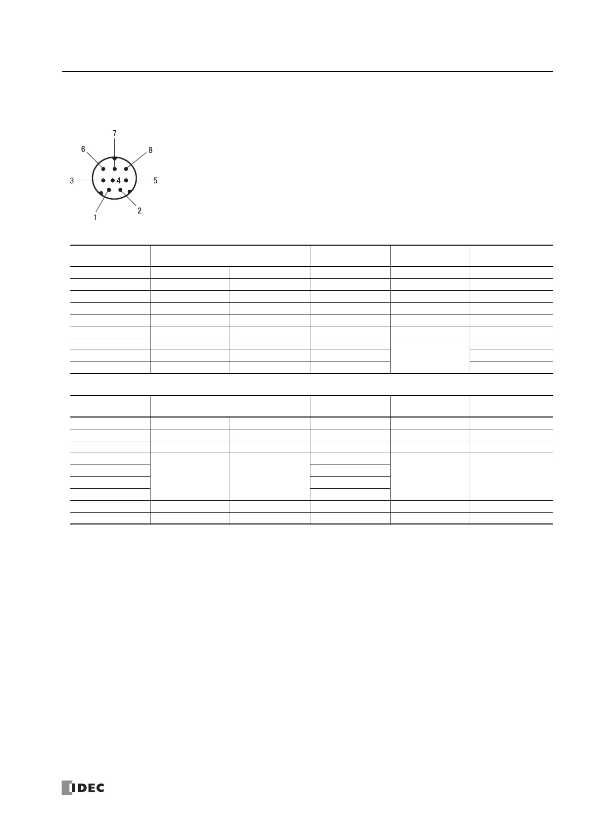
Expansion Communication Port Wiring Diagram
The mini-DIN connector pin assignments and signal names are as follows.
RS232C (FT1A-PC1)
RS485 (FT1A-PC2)
Note: Do not connect cables to NC. There is a risk of malfunction or failure.
Pin Number Signal Name Cable Color Signal Direction
Peripheral Device
(D-SUB)
Cover Port 2 Port 3 Shield — RS232C
1 RS (RTS) RS (RTS) Black → (DR)
2 ER (DTR) ER (DTR) Yellow → (CTS)
3 SD (TXD) SD (TXD) Blue → RD
4 RD (RXD) RD (RXD) Green ← SD
5 DR (DSR) DR (DSR) Brown ← RS
6SGSGGray
None
SG
7SGSGRed SG
8NCNCWhite NC
Pin Number Signal Name Cable Color Signal Direction
Peripheral Device
(D-SUB)
Cover Port 2 Port 3 Shield — RS485
1AABlack←→ A
2BBYellow←→ B
3
NC NC
Blue
NC
4Green
5Brown
6Gray
7SGSGRed—SG
8 NC NC White None NC