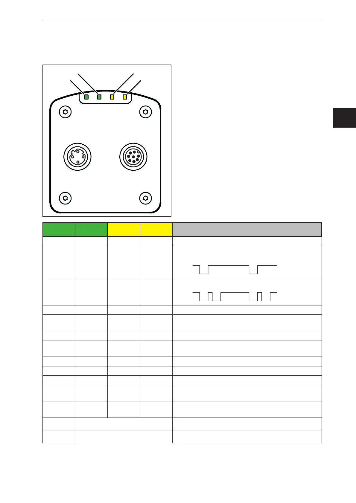
LED 4
(Ethernet)
LED 1
(Power)
LED 2
(Out 1)
LED 3
(Out 2)
Description
On Sensor is ready for operation, supply voltage applied
Flashes
at 0.5 Hz
No parameters set or parameter setting was not
loaded into the sensor
On Switching output 1 switched
Flashes
at 8 Hz
Switching output 1 shorted
On Switching output 2 switched
Flashes
at 8 Hz
Switching output 2 shorted
On Ethernet connected
Flashes Ethernet transmitting data
Off Ethernet not connected
Flashes
at 8 Hz
Flashes
at 8 Hz
Sensor signals internal error
Flashes
at 2 Hz
Flashes
at 2 Hz
Sensor signals correctable error. The error information
can be read via Ethernet
Running light ⇒
Device booting
Running light ⇐
Sensor carrying out firmware update