3D sensor
16
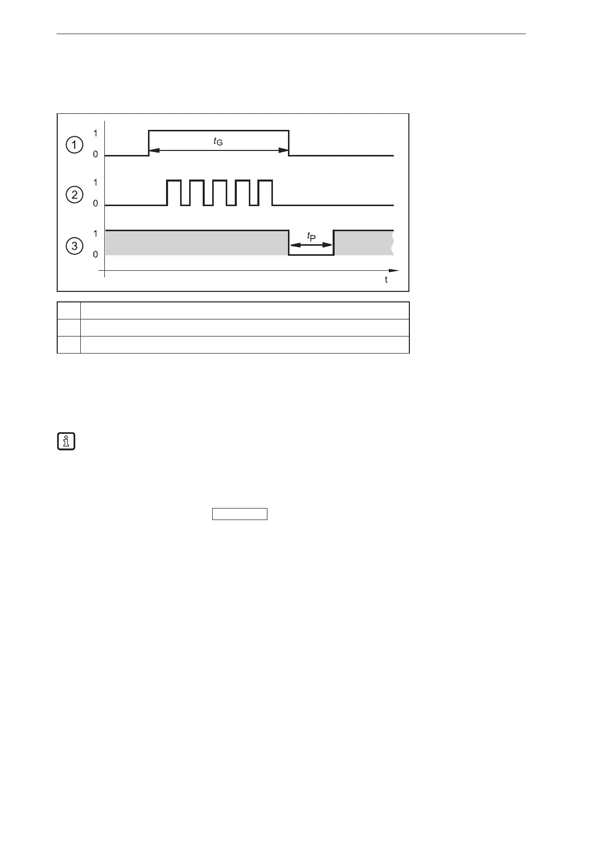
7.4 Pulse-controlled selection of the application
As an alternative to the static selection the selection of the application can also be pulse-controlled.
1 2345
①
Gate signal, switching input 1 = 0 → 1 → 0 (t
G
= signal active)
②
Pulse signal, switching input 2 or trigger input = 0 → 5 pulses → 0
③
READY output
While there is an active signal on switching input 1 (gate signal), the device counts incoming pulses and
activates the respective application.
Number of pulses = ID number of the application
Either switching input 2 or the trigger input of the device can be used as pulse input.
The figure above shows the PNP output logic (factory setting). The behaviour of the NPN output
logic is the opposite of that of the PNP output logic:
● PNP output logic: In case of a high signal (1), voltage is applied.
● NPN output logic: In case of a low signal (0), voltage is applied.
For more detailed information about the configuration of the selection of the application we refer you to
the software manual of the device.
www.ifm.com