55
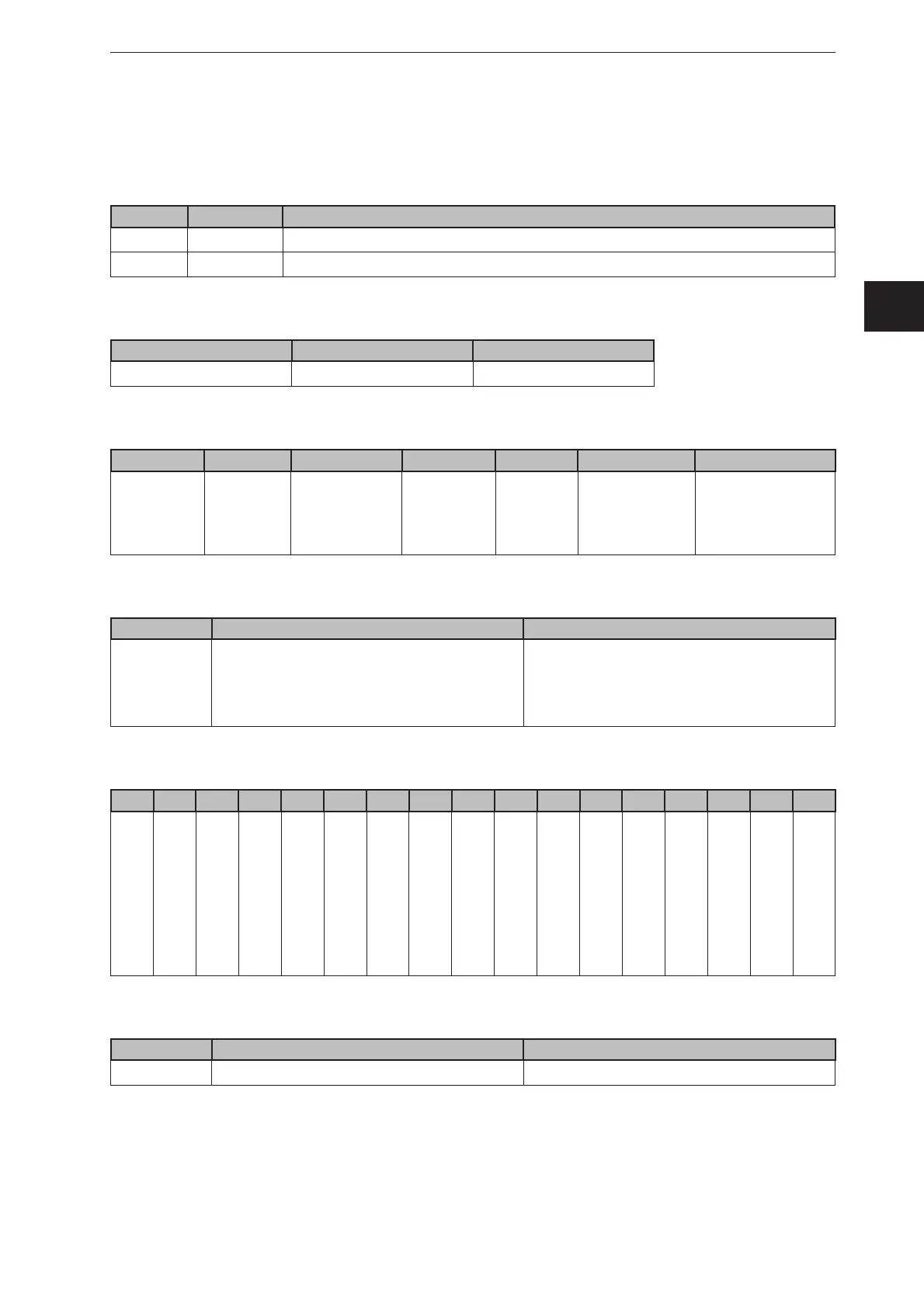
3D sensor
UK
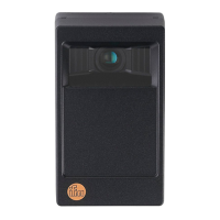
13.4 EtherNet/IP
13.4.1 Data structures for consuming and producing assemblies
Assemblies
Instance Bytes Type
100 8 Consuming (from device point of view: databuffer for receiving from PLC)
101 450 Producing (from device point of view: databuffer for sending to PLC)
Consuming assembly data layout
Byte 0-1 2-7
Description Command word Command data
Layout of producing assembly
Byte 0-1 2-3 4-5 6-7 8-15 16-449
Description Command
word for
mirroring
Synchronous /
asynchronous
message
identifier
Message
counter
Reserved Mandatory
message data
(e.g. error code)
Non mandatory
data fields
Layout of command word
Bit 0 1-15
Description Error bit
This bit has no meaning in the consuming
assembly. It is used for signaling an
occured error to the PLC
Command bits
Each bit represents a specific command
Command word
Bit 0 1 2 3 4 5 6 7 8 9 10 11 12 13 14 15
Description
Error bit
N.a.
N.a.
N.a.
N.a.
N.a.
Get last error
Get connection ID
Get statistics
Activate application
Get application list
Get IO state
Set IO state
Execute synchronous
trigger
Activate asynchronous
PCIC output
N.a.
Synchronous / asynchronous message identifier
Bit 0 1-15
Description Asynchronous message bit Bits for asynchrounous message identifier
Data to send exceeds processing assembly data section size
If the size of the data exceeds the size of the configured processing assembly data section size, the data
is truncated. No error is risen.