3D sensor
14
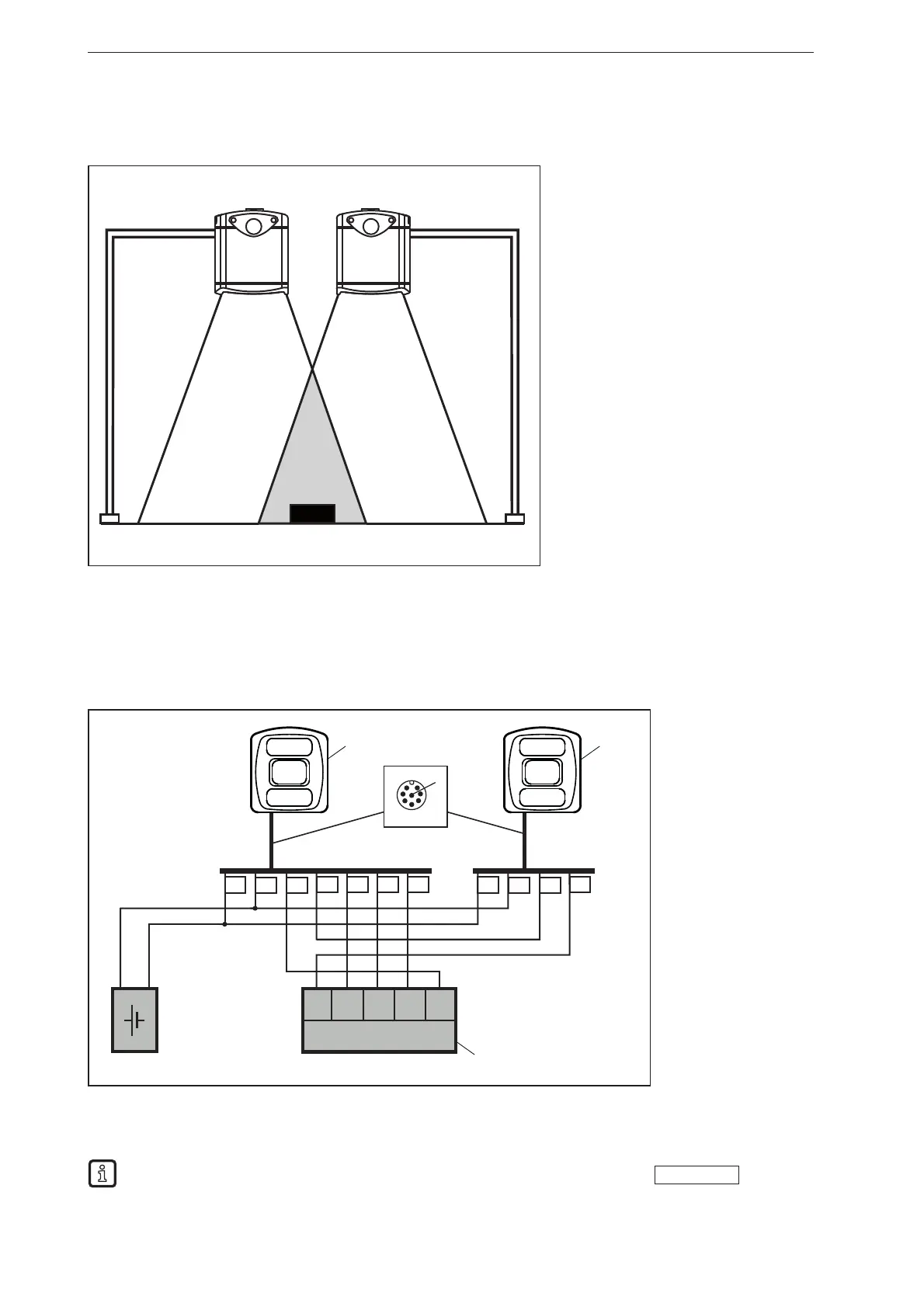
7.2.2 Install several sensors next to each other
Sensors installed next to each other can cause measurement errors due to simultaneous exposure.
① Device
② Device
③ Object
The measurement errors can be avoided in two ways:
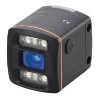
● Cascade sensors via HW trigger
During cascading a controller triggers the image capture of sensor ① (see figure below). After
completion of the image capture, sensor ① automatically triggers sensor ②. At the same time, pin
4 of sensor ① provides the sensor status "Image capture finished". Sensor ② signals the end of the
sequence to the industrial controller ③.
3 1 2 4 5
DC 24 V
+
-
3 1 2 5
① Device
② Device
③ Industrial
controller
(evaluate /
trigger)
● Use different frequency channels
With the software ifm Vision Assistant each sensor can be assigned its own frequency channel. The
different frequency channels reduce the occurrence of measurement errors.
The ifm Vision Assistant software is available free of charge on our website:
www.ifm.com