9 SOFTWARE CONFIGURATION
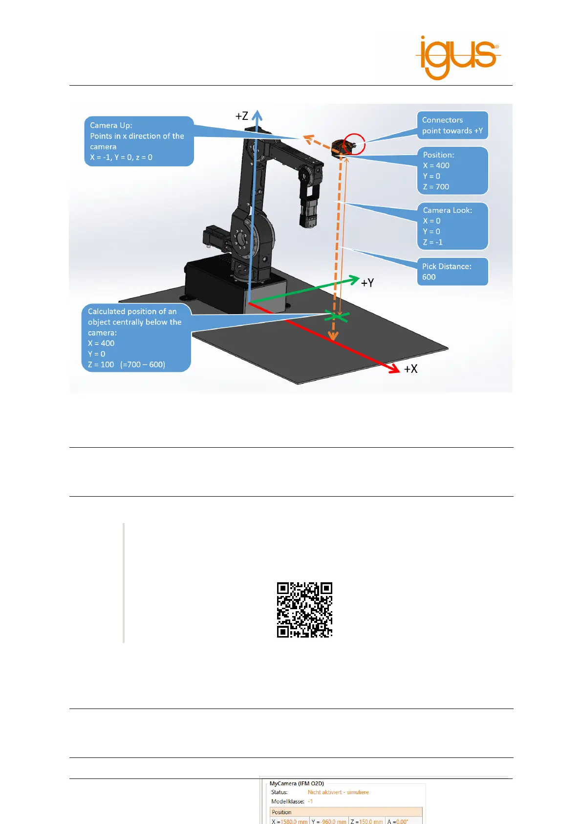
Figure 28: Measuring the camera position and orientation.
Parameter Meaning
Look Viewing direction of the camera. A downward pointing camera has Z=-1
Up X Direction of the camera in the robot coordinate system
Z Distance Distance of the objects from the camera
For step-by-step instructions and tips on parameterization, please refer to our Wiki ar-
ticle:
https://wiki.cpr-robots.com/index.php/2D_Camer
a_Integration
The simulation section enables the simulation of the camera. This function is not available in the
integrated control.
Parameter Meaning
SimX, SimY Object position in pixels (0-640 and 0-480 respectively)
SimA Orientation in degrees
Model class Class of detected object, the value -1 means no object is recognized.
After configuration, the detected and
calculated values can be observed in the
status area. Images received from the
camera are displayed here.
Figure 29: Camera status area
Camera Interface for USB Video
USB video class (UVC) cameras can be used to observe the work area, for example webcams or in-
dustrial USB video cameras. The robot controller forwards the received images via the following in-
terfaces:
• CRI interface: The image is transmitted via the Ethernet interface to iRC and can be observed
there in the camera status area (see fig. 29).
• Cloud interface: When this is enabled and the camera is assigned the image is transmitted to
the RobotDimension cloud. The image can be monitored via the website (see section 9.2.7).
Compatibility:
The USB camera interface is only supported by integrated controllers based on the
Raspberry Pi. Older robot controllers controlled by a Phytec module do not support
USB cameras. The Windows software iRC does not support this camera interface ei-
ther, here USB cameras can be assigned directly in the cloud configuration area (see
section 9.2.7).
©2022 igus® GmbH 45