.J
l
]
HTM-1505R/HTM-1505CS
@ YPbPr/RGB switch
• To select YPbPr/RGB input, turn it on.
Set switching ofYPbPr and RGB on MENU-Item 4.
Setting of INT/EXT of SYNC is memorized at each channel (A, B)
in case of YPbPr/RGB input and changes to setting side simul-
taneously with channel switching automatically.
Setting of 4:3/16:9 of ASPECT is memotized at each channel
regardless of format and changes to setting side simultaneously with
channel switching automatically.
@ 2nd SLOT switch
When 2 kinds of SDI modules (exan1ple: DKM-50l+DK-801) or 2
kinds of decoder modules (example: DE-S0l+DE-802) are mounted,
2nd SLOT is changed by means of this switch.
a) In case of SDI module
SD-SDI is assigned to 2nd SLOT.
b) In case of decoder module
DE-802 is assigned to 2nd SLOT.
@ TEST switch
18
To change to built-in TEST signal, turn it on.
• TEST signal (standard) incorporates the following format:
Set switching on MENU-Item 5.
525i/59.94
625i/50
1035i/60
1080i/60
720p/60(Type-l only)
Setting of 4:3/16:9 of ASPECT is memorized at each channel
regardless of format and changes to setting side simultaneously with
switching automatically.
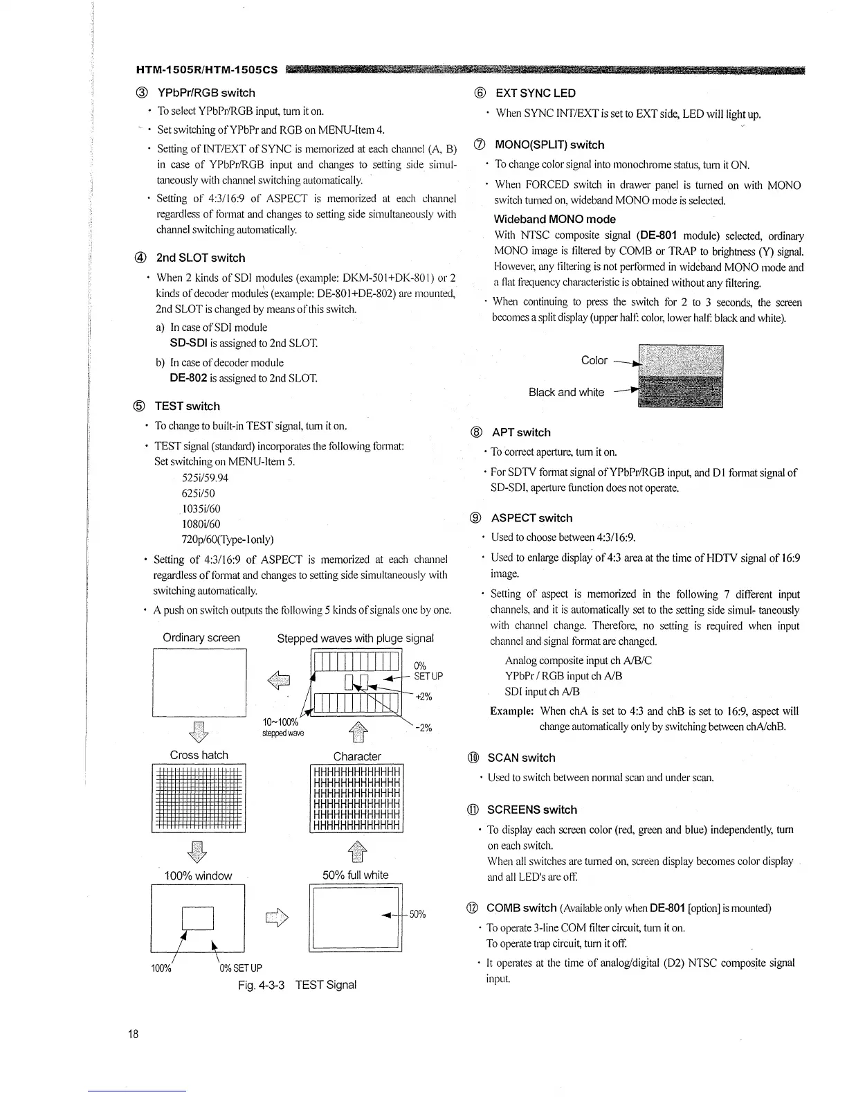
A push on switch outputs the following 5 kinds of signals one by one.
Ordinary screen
[J
"
Cross hatch
•
"'
100%window
100% 0% SET UP
~
~
10~100%
stepped wave
Character
HHHHHHHHHHHHH
HHHHHHHHHHHHH
HHHHHHHHHHHHH
HHHHHHHHHHHHH
HHHHHHHHHHHHH
HHHHHHHHHHHHH
~
50% full white
0%
SETUP
+2%
-2%
$[]m
Fig. 4-3-3 TEST Signal
@ EXT SYNC LED
• When SYNC INT/EXT is set to EXT side, LED will light up.
(/) MONO(SPLIT) switch
• To change color signal into monochrome status, tum it ON.
· When FORCED switch in drawer pru:iel is tumed on with MONO
switch turned on, wideband MONO mode is selected.
Wideband MONO mode
With NTSC composite signal (DE-801 module) selected, ordinary
MONO image is filtered by COMB or TRAP to btightness (Y) signal.
However, any filtering is not perfo1med in wideband MONO mode and
a flat frequency characteristic is obtained without any filtering.
• When continuing to press the switch for 2 to 3 seconds, the screen
becomes a split display (upper half:. color, lower halt: black and white).
Color
Black and white -
@ APTswitch
• To con-ect aperture, tum it on.
• For SDTV format signal ofYPbPr/RGB input, and DI format signal of
SD-SDI, aperture function does not operate.
@ ASPECT switch
Used to choose between 4:3/16:9.
Used to enlarge display of4:3 area at the time of HDTV signal of 16:9
image.
Setting of aspect is memorized in the following 7 different input
channels, and it is automatically set to the setting side simul~ taneously
with channel change. Therefore, no setting is required when input
channel and signal format are changed.
Analog composite input ch A/B/C
YPbPr I RGB input ch A/B
SDI input ch A/B
Example: When chA is set to 4:3 and chB is set to 16:9, aspect will
change automatically only by switching between chA/chB.
@ SCAN switch
• Used to switch between nonnal scan and under scan.
@ SCREENS switch
• To display each screen color (red, green and blue) independently, turn
on each switch.
When all switches are turned on, screen display becomes color display
and all LED's are oft:
® COMB switch (Available only when DE-801 [option] is mounted)
· To operate 3-line COM filter circuit, tum it on.
To operate trap circuit, turn it oft:
It operates at the time of analog/digital (D2) NTSC composite signal
input.
 Loading...