HTM-1505R/HTM-1505CS
@ Adjustment of highlight portion
·Turnoff SET-UP switch and each SCREEN switch.
36
• Observe the highlight portion of stepped wave and actjust so that it
may become the intended color temperature by means of GAIN of
G and B.
@ Adjustment oflow light portion
Observe the low light po1tion of tone wave ahd ac[just so that it
may become the intended color temperature by means of
BACKGROUND ofR, G and 8.
(J) As adjustments @ and @ interfere each other, repeat ac(just-
ments @ and @ until the intended color temperature can be
attained from the low light po1tion to the highlight prntion.
c) Adjustment procedure-2 -Ac(justment using color analyzer
When ac(justing color When chromaticity point converges to the
rated value for both low light and highlight, ac(justment has been
completed.:
CIE chromaticit oint to color temperature (x, y)
-~?ti~{~:j?:;:Jf?#l~t ;.;J\t·t;r~r::-r~·:-"
0.313 0.329
0.283
0.297
Q) lnputSignal
Input a window signal or select the window signal of the built-in
test signal.
® Setting a file
Select a file for which white balance is changed.
Control brightness and contrast properly before white balance
ac(justment
@ Adjustment ofR.BACKGROUND
As white balance is ac(justed on the basis of red, set R.BACK-
GROUND here.
• Turn on SET-UP switch in the drawer panel, and set to the status
shown in Fig. 4-10-2.
• With SCREEN switch (Red) alone turned on (only red screen),
adjust R. BACKGROUND data to such a degree that the red line
in portion B in Fig. slightly glares.
· Return the status of SET-UP and each SCREEN switch to the
former status, and do not move R.BACKGROUND any more.
© Setting of Contrast
Set CONTRAST to manual status, apply the probe of color analy-zer
to the center of window signal indicated on the screen, and set the
brightness value by manual operation beforehand so that brightness
value may be set to about 5 nit( ccVm
2
) or about 1.5 tL.
As the brightness value set here changes according to the
ac(justment of white balance. check it each time low light portion
is ac(justed, and set it again if it deviates. Pen11issible value of
deviation is about ±2nit(±0.5JL).
@ Setting of chromaticity point at the time of highlight (x, y)
Set CONTRAST to the preset status and set chromaticity point (x,
y) at the time of highlight with GAIN ofG and 8.
-1. Ac(just so that chromaticity point x may become the rated value
with B.GAIN.
-2. Ac(just so that chromaticity pointy may become the rated value
with G.GAIN.
-3. Adjust chromaticity point (x, y) repeatedly until it converges to
the rated value.
@ Setting of chromaticity point at the time of low light (x, y)
Set CONTRAST to the manual status and set chromaticity point (x, y)
at the time of low light with GAIN ofG and B.
-1. Ac(just so that chromaticity point x may become the rated value
with B.BACKGROUND.
-2. Ac(just so that chromaticity point y may become the rated value
with G.BACKGROUND.
-3. Ac(just chromaticity point (X:, y) repeatedly until it converges to the
rated value.
When this low light portion is ac(justed, chromaticity point at the time
of highlight will also shift. So, when it comes near to the rated value
at the initial ac(justment, adjust the highlight portion of Step @
again.
(J) When chromaticity point converges to the rated value for both low
light and highlight, ac(justment has been completed.
(4) Color balance adjustment
a) About the color balance
For component signal (YPbPr/RGB), color balance is adjusted only by
CHOROMA. However, when NTSC decoder module [DE-801]
capable of inputting NTSC composite signal is mounted, adjust color
balance by the adjustment of HUE and CHROMA.
b) Adjustment procedure - I ~In case ofNTSC composite signal-
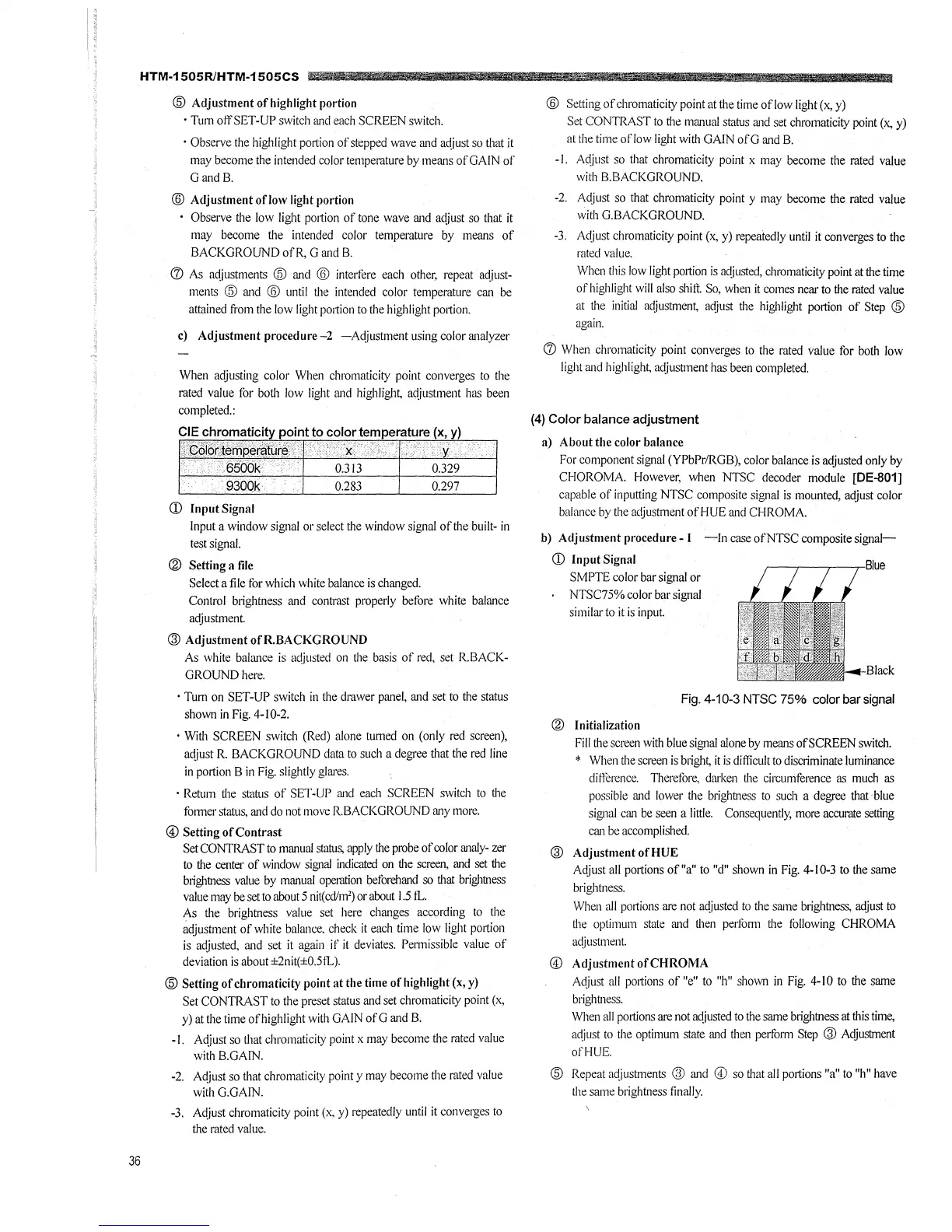
CD Input Signal
SMPTE color bar signal or
NTSC75% color bar signal
similar to it is input.
Black
Fig. 4-10-3 NTSC 75% color bar signal
® Initialization
Fill the screen with blue signal alone by means of SCREEN switch.
* When the screen is brigh~ it is difficult to discriminate luminance
difference. TI1erefore, darken the circumference as much as
possible and lower the brightness to such a degree that-blue
signal can be seen a little. Consequently, more accurate setting
can be accomplished.
@ Adjustment of HUE
Adjust all portions of"a" to "d" shown in Fig. 4-10-3 to the same
brightness.
When all prntions are not ac(justed to the same brightness, ac(just to
the optimum state and then perfo1111 the following CHROMA
ac(justment.
© AdjustmentofCHROMA
Adjust all prntions of "e" to "h" shown in Fig. 4-10 to the same
brightness.
When all portions are. not ac(justed to the same brightness at this time,
ac(just to the optimum state and then perfo1111 Step @ Ac(justment
ofHUE.
@ Repeat ac(justments ® and © so that all portions "a" to "h" have
the same brightness finally.