38
HTM-1505R/HTM-1505CS ii&
sttliF
(7) Screen Center adjustment
a) About the screen center
To ac(just the screen cente1; use the following 3 kinds of controllers:
In addition, sd data for each signal fonnat.
H.PHASE
Ac\just the position of image so that the phase of I 00% marker
may agree with the image.
H.CENT
Adjust the position of horizontal deflection to the frame of
escutcheon (whole surface frame of CRT) so that the marker may
come to the center of the whole surface frame.
V.CENT
Adjust the position of vertical deflection to the frame of
escutcheon (whole swiace frame of CRT) so that the marker may
come to the center of the whole surface frame.
b) Note
As I-I. PHASE and VCENT are saved as data for each signal
format, do not pe1form the Jollowing switching operation during
setting.
If switching operation is performed, ditlerent data than the format
that has been set up to now is called, and thus data that is used during
operation will be cleared.
• Channel switching
· Change of input signal format
· SCAN switching
• ASPECT switching
c) Adjustment procedure
The following ac(justment is an ac(justment procedure for one signal
format. Howeve1; it is possible to set other signal formats in
accordance with the same method as well, respectively.
CD Input Signal
• Check that the format of MENU I is correctly set to the signal
fonnat to be changed.
For format setting, refer to 4 -11 (3).
• Input a signal (mono-scope signal etc.) of which video com-
ponent can indicate the whole available picture area
@ Adjustment ofH.CENT/Y.CENT
-1. Set the size to normal size with SCAN switch.
-2. Tum on MARKER switch and indicate I 0-divided cross-
hatching.
-3. Adjust horizontal direction by H.CENT and vertical direction by
VCENT so that the upper and lower sides and the right and left
sides may be equal.
-4. As the following adjustment @ changes to the under-scan size
with SCAN switch, press CHANGE PRESET switch
beforehand to save data
<OK>
Utd
¥Mi
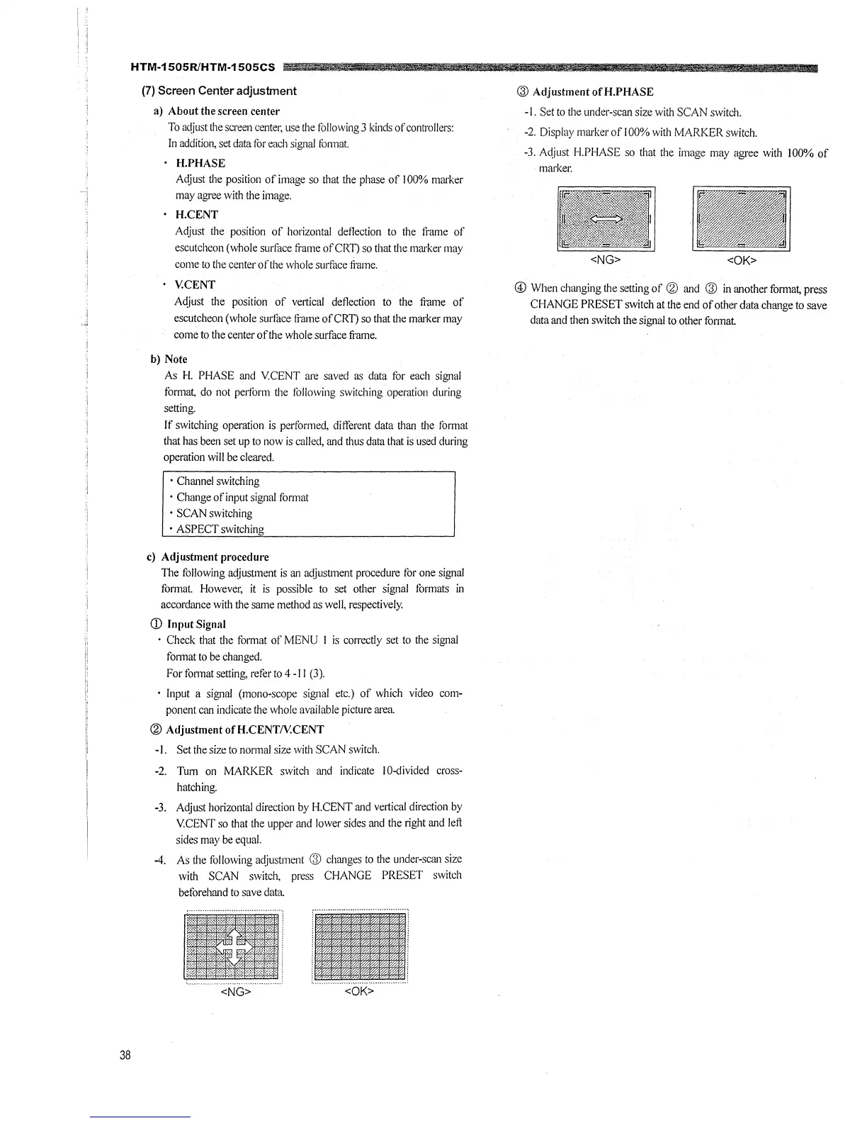
@ Adjustment ofH.PHASE
-1. Set to the under-scan size with SCAN switch.
-2. Display marker of I 00% with MARKER switch.
-3. Adjust I-I.PHASE so that the image may agree with 100% of
markec
<NG>
@ When changing the setting of @ and @ in another format, press
CHANGE PRESET switch at the end of other data change to save
data and then switch the signal to other format.