HTM-1505R/HTM-1505CS lJ!. r
(8) Functional description of MENU6
46
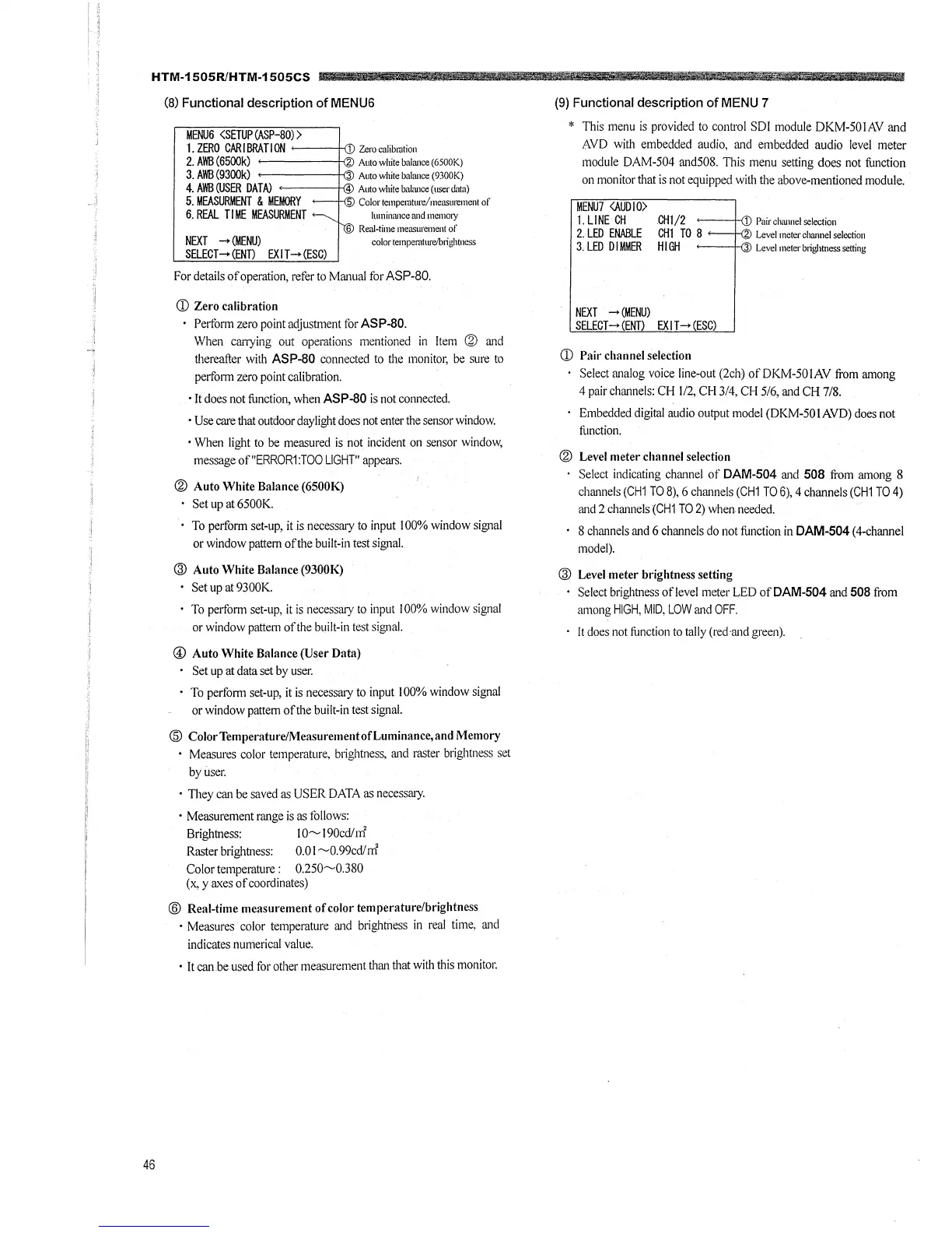
MENU6 <SETUP (ASP-80) >
1. ZERO CAR I BRA Tl ON <-----+ii
I
Zero calibmtion
2. AWB (6500k) Auto white balance (6500K)
3. AWB (9300k) Auto white balance (9300K)
4. AWB(USER DATA) Autowhitebalance(userdata)
5. MEASURMENT & MEMORY 5 Colorternpemture/rneasurement of
6. REAL TIME MEASURMENT
NEXT -+ (MENU)
SELECT-+ (END EXIT-+ (ESC)
luminru1ce and 111en101y
6 Real-time measurement of
color te1npemturelb1ight11ess
For details of operation, refer to Manual for ASP-80.
CD Zero calibration
Pe1iorm zero point adjustment for ASP-80.
\Vhen Cat7ying out operations mentioned in lten1 @ and
thereafter with ASP-80 connected to the monitor, be sure to
perfmm zero point calibration.
• It does not function, when ASP-80 is not connected.
• Use care that outdoor daylight does not enter the sensor window.
• When light to be measured is not incident on sensor window,
message of"ERROR1:TOO LIGHT" appears.
® Auto White Balance (6500K)
Set up at 6500K.
To perform set-up, it is necessary to input I 00% window signal
or window pattern of the built-in test signal.
@ Auto White Balance (9300K)
Set up at 9300K.
To pedonn set-up, it is necessary to input I 00% window signal
or window pattern of the built-in test signal.
© Auto White Balance (User Data)
Set up at data set by user.
To perfonn set-up, it is necessary to input I 00% window signal
or window pattern of the built-in test signal.
@ Color Temperature/Measurement of Luminance, and Memory
• Measures color temperature, brightness, and raster brightness set
by user.
· They can be saved as USER DATA as necessruy.
• Measurement range is as follows:
Brightness: IO~ l 90cd/ rrl'
Raster brightness: 0.01 ~0.99cd/rrl'
Color temperature : 0.250~0.380
(x, y axes of coordinates)
@ Real-time measurement of color temperature/brightness
• Measures color temperature ru1d brightness in real time, ru1d
indicates numerical value.
• It can.be used for other measurement than that with this monitor.
ll
(9) Functional description of MENU 7
* This menu is provided to control SDI module DKM-501AV and
AVD with embedded audio, and embedded audio level meter
module DAM-504 and508. This menu setting does not function
on monitor that is not equipped with the above-mentioned module.
MENU7 <AUD I O>
1.LINE CH
Pair channel selection
2. LED ENABLE
3. LED DIMMER
CHl/2
CHl TO 8
HIGH
Level meter channel selection
<---+-n1 Level meter b1ightness setting
NEXT -+ (MENU)
SELECT-+ (ENT) EXIT-+ (ESC)
CD Pair channel selection
Select ruialog voice line-out (2ch) ofDKM-501AV from runong
4 pair chru1nels: CH 1/2, CH 3/4, CH 5/6, and CH 7/8.
Embedded digital audio output model (DKM-50 IAVD) does not
tlmction.
® Level meter channel selection
Select indicating channei of DAM-504 ru1el 508 from among 8
channels (CH1 TO 8), 6 chrumels (CH1 TO 6), 4 channels (CH1 TO 4)
and 2 chrumels (CH1 TO 2) when needed.
8 channels and 6 channels do not function in DAM-504 ( 4-channel
model).
@ Level meter brightness setting
Select brightness oflevel meter LED ofDAM-504 ru1d 508 from
among HIGH, MID. LOW ru1d OFF.
It does not fonction to tally (red·ru1d green).