18
Quick Measure
Explanation of Function
Use Quick Measure for measuring flow, differential pressure (∆p) and temperature in a waterborne heating/cooling
system. The function also provides a measuring method for estimating power.
Quick Measure is the preferred method for separate measurements on a few selected valves. For example when
performing control or inspection of a balanced system.
Measure Flow
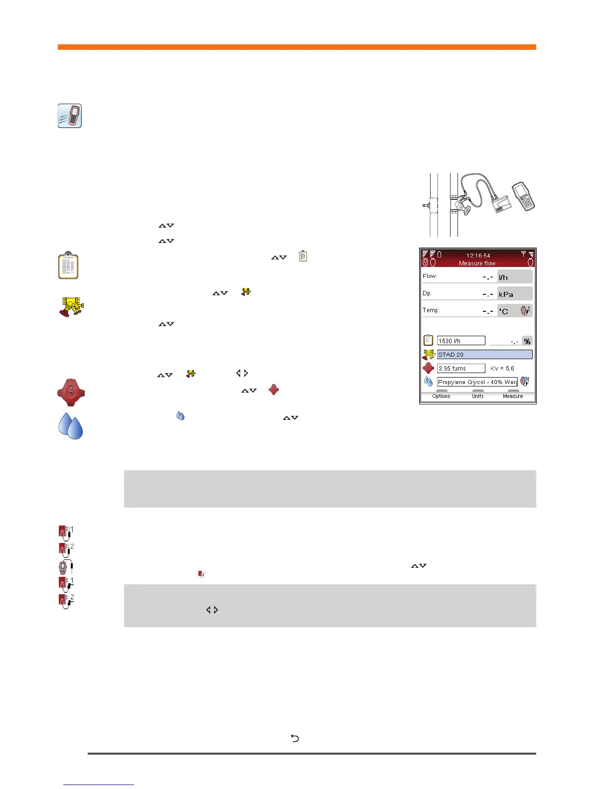
1 Connect measuring equipment depending on desired measurement.
The Measure Flow function enables a combined measurement of
differential pressure (∆p), flow and temperature. More connecting details on
page 15.
2 Navigate
to Quick Measure in the main menu and press enter.
3 Navigate
to Measure Flow and press enter.
4 Optionally input Design Flow. Navigate
to and type the given design
flow for the terminal. While measuring the deviation is given in percent besides
the entered design flow.
5 Define valve. Navigate
to and press enter.
6 Select input field for Type and press enter.
7 Navigate
to desired valve type and press enter.
8 Continue by defining Family and Valve in the same way.
9 Make valve settings valid by pressing the function key Done. Valve settings are
visible in the Measure Flow menu. Valve size can easily be changed from here,
navigate
to and cycle the options. Type and family stays the same.
10 Input Valve Opening. Navigate
to and type the number of turns stated
at the digital read-out at the handwheel, more handwheel details on page 16.
11 Define fluid in
. Press enter and navigate to input fluid temperature and properties. Press enter.
12 Freezing point is stated below the temperature input field and the auto correction function indicates if the allowed
limits are exceeded. More Fluid details on page 34.
13 Press function key Done to make fluid definition valid.
14 Press function key Measure to start measuring.
15 After the calibration cycle is done the measurement begins and values are displayed for Differential Pressure (∆p),
Flow and optional Temperature if the temperature sensor(s) is connected.
16 If multiple temperature sensors are connected, cycle the sensors by navigating
to the temperature row and
press enter. An icon indicates which of the sensors is currently showing a temperature reading.
17 Press function key Hold to pause the measuring, and press Continue to resume.
18 Save measurements
• Press function key Save to store the measured data for future needs.
• Enter a name for performed measurement. Date and time is automatically added.
• If the name entered is already used, an overwrite request is displayed.
• Optionally enter a description.
• Press function key Save, the measurement is saved and measuring menu appears again.
19 End measurement by exiting the menu, press
and disconnect the measuring points according to page 15.
Note! Remember to always update fluid properties according to the system currently being
measured.
!
Tips! Short cut to increase/decrease valve size and valve turns from the measuring menu
– press when the input field is in focus.
!
Quick Measure