29
Troubleshooting
Explanation of Function
Troubleshooting is all about measuring relevant hydronic data and making use of them to deduce the origin of
hydronic problems. It is a key functionality provided by TA-SCOPE.
The TA-Diagnostic method is an evolution of the well-known TA Balance method that takes you valve by valve,
module by module through the plant. Easy-to-follow step-by-step instructions are displayed on TA-SCOPE. The
TA-Diagnostic method delivers a Dp map for locating and diagnosing problems in each hydronic module on which
it is used.
Software wizards are also available in the TA-SCOPE taking you step-by-step through the process of diagnosing
problems and errors in a hydronic circuit.
Diagnose a Hydronic Network with TA-Diagnostic
The TA-Diagnostic method is a balancing and diagnostic method. It can be started either from Troubleshooting
or from Balancing in the main menu, see page 25 for a detailed description. The method and required actions are
the same.
Use the Required Dp on Circuit Troubleshooting Wizard
This troubleshooting wizard is to be used when design flow cannot be obtained in a circuit. Based on two
measurements, it allows determining the Differential Pressure (Dp) to be applied on a circuit in order to reach the
design flow. Required equipment is a flow measuring valve in the circuit that can be installed on supply or return
side and one measuring point on the other side.
1 Select
Troubleshooting from the main menu. Press enter.
2 Select
Required Dp on circuit. Press enter.
3 Ensure the required equipment listed on screen is available on the
circuit, press function key Continue.
4 Connect the Dp sensor as shown on screen. Note that you will need to
adjust the valve setting in the next step in order to reach a minimum Dp
usually set at 3 kPa. Press function key Continue.
5 You are in the Measure flow screen. You can input design flow, change valve type and diameter, input valve
setting and define the fluid. Follow steps 4 to 14 from Measure flow section in page 18.
6 After the calibration cycle is done the measurement begins and values are displayed for Differential Pressure (Dp),
Flow and optional Temperature if the temperature probe(s) is connected.
7 Adjust and input accordingly valve opening until you obtain more than 3 kPa in the valve. Press function key
Continue.
8 Connect the Dp sensor as instructed on screen in order to measure
the current Differential Pressure (Dp) of the circuit, press function key
Continue.
9 After the calibration cycle is done the measurement begins and a value
is displayed for Differential Pressure (Dp). Press function key Continue.
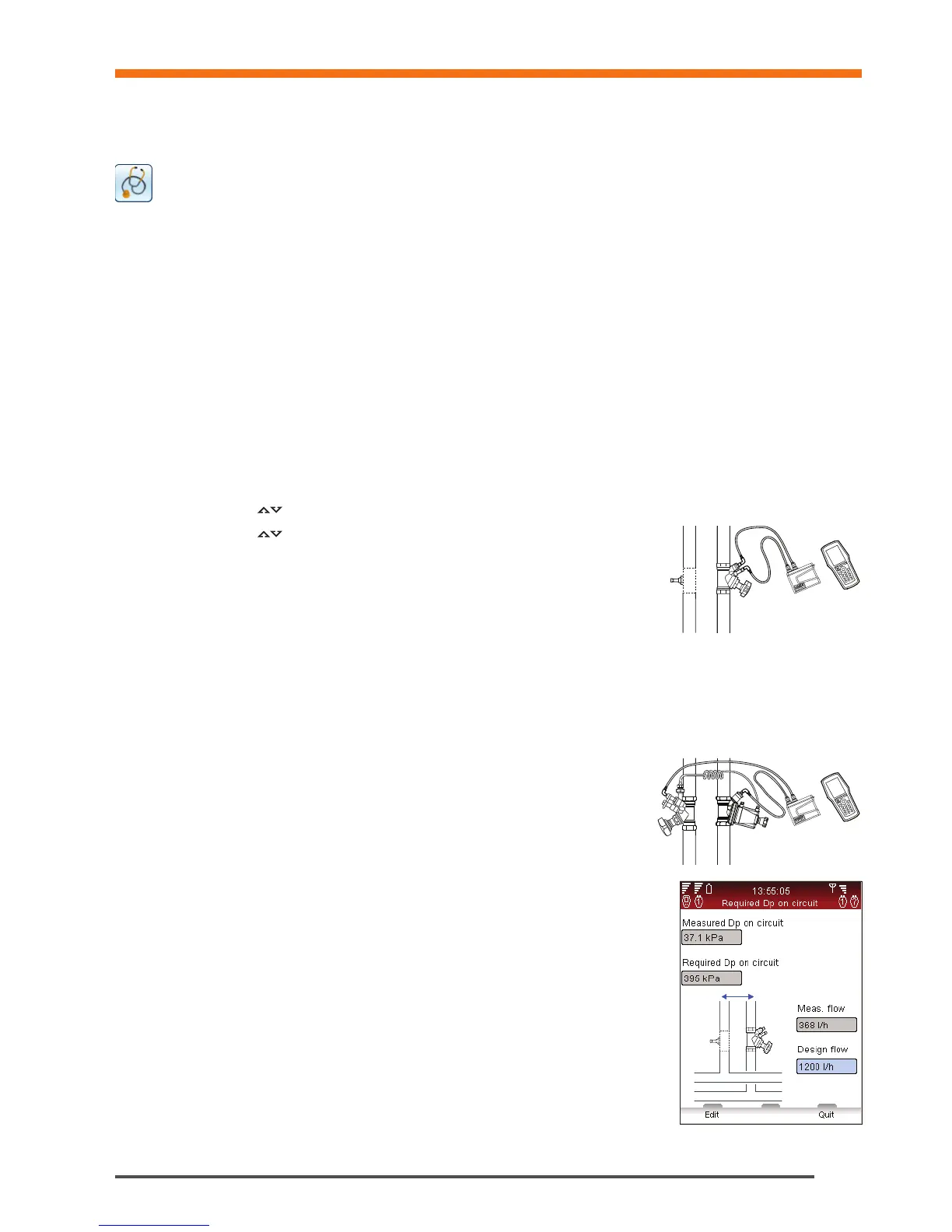
10 Troubleshooting data are displayed. Measured Dp on circuit and
Measured flow are the two measurements you have just performed. Required
Dp on circuit is the Differential Pressure (Dp) that will be required on the circuit
in order to be able to reach the design flow you have input. You can input
another design flow to examine the corresponding required Differential Pressure
on the circuit.
Troubleshooting