25
Balancing
Explanation of Function
Balancing is one of the main functions in TA-SCOPE. It is a systematic methodology to ensure that the hydronic
system actually performs as specified by the designer and provides the desired indoor climate at the lowest
possibly energy cost.
The TA-Diagnostic and TA-Wireless methods provide a survey of the entire hydronic system and take you valve by
valve, module by module through the plant. Easy-to-follow step-by-step instructions are displayed on TA-SCOPE.
Balancing can be performed both in Hydronic Networks created and downloaded from HySelect and also on
modules defined on site with your TA-SCOPE.
Prerequisites for Balancing
There are several important system requirements which should be ensured before starting the balancing process.
• Variable speed pump is at full speed (set-point will be optimised after balancing).
• Control valves are fully open.
• Partner valve is fully open.
• Balancing valves of the module are all set at half-opening or at calculated presetting opening (optional for
TA-Wireless method).
• The right media/fluid temperature in cooling system.
Balance a Hydronic Network with TA-Diagnostic
The TA-Diagnostic method is an evolution of the TA Balance method. The TA-Diagnostic method provides
automatic calculation of valve handwheel settings module by module for the entire hydronic system to ensure
design flow is available at all terminal units. It also delivers a Dp map for locating and diagnosing problems in
hydronic modules.
When balancing a predefined hydronic network the action can be started either from the Balancing function, as
described below, or directly from the function Hydronic Networks, see page 23. The method and required
actions are then the same.
1 Select
Balancing from the main menu, press enter.
2 If required, adjust the acceptable flow deviations in design conditions with
Balancing Tolerance (also available in Settings menu, see page 37).
3 Select TA-Diagnostic method. Press enter.
4 A general description of the TA-Diagnostic method is displayed. Press function key Continue.
5 A drop-down list of networks stored in your TA-SCOPE is displayed. Navigate
to desired network and press enter.
If no Hydronic Network is stored the only available option is New Hydronic Network.
6 Select An existing module, press enter.
7 The selected network appears on the display. Expand
the network and navigate
to the module where the balancing should start from.
8 Ensure the essential balancing prerequisites displayed in the list are fulfilled, press
function key Continue.
9 A list of options appears on the display. Select Perform Balancing and press enter.
10 The selected module appears on the display. Navigate
to the first valve you wish to
measure on and press enter.
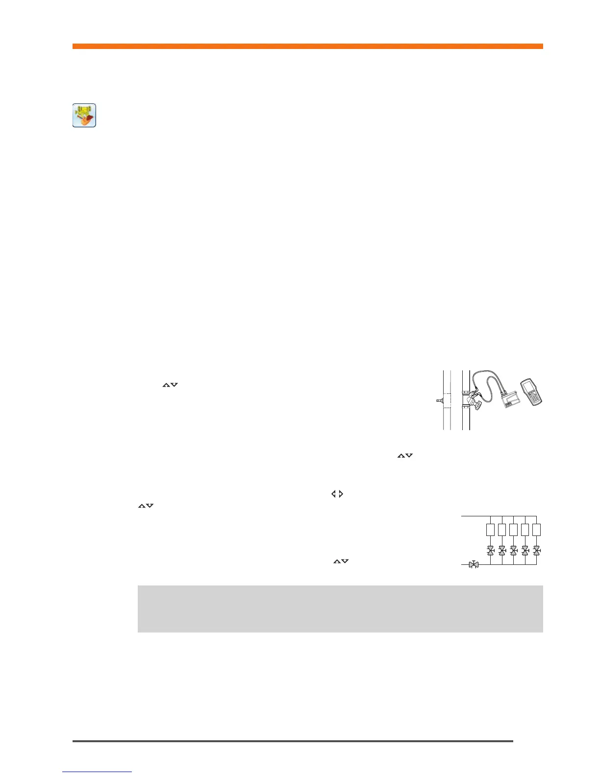
11 Connect the measuring equipment to the first valve you wish to measure on, see page 15 for connection details.
12 System properties including design flow, valve type and valve opening for the selected valve are displayed.
13 Press the function key Measure.
Balancing
Tips! In the TA-Diagnostic method valves can be measured in any order but numbering must
follow the correct order starting at 1 at the entry of the module and incrementing by 1 for each
next valve as we progress towards the end of the module.
!
1 2 3 4 5