9
Guide to Manual and Instrument
Guide to Manual and Instrument
General Instrument Instructions
TA-SCOPE facilitates effortless performance of all hydronic functions through easy to navigate menus.
Handheld
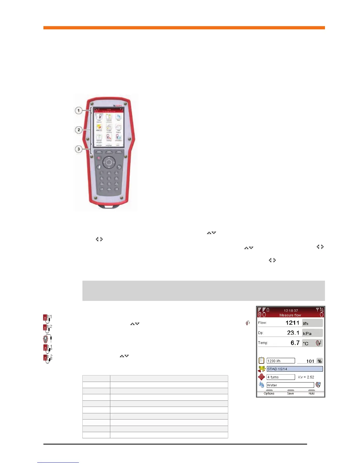
The display is divided into three areas, the Information bar, the Main display and the Function keys.
1 – Information bar
Icons on the Information bar display details of battery status, connection type and
intensity.
2 – Main display
Instructions on how to carry out hydronic functions are shown on the Main display.
3 – Function keys
The three top keys on the key board are used for selecting options shown in the lower
part of the Main display. The options vary depending on which menu is currently shown.
Keypad
• The keypad has alphanumeric keys. Select a letter by repeatedly pressing the key
until the desired letter appears. Prolonged press enters a digit.
• Dot key works as caps lock. For a dot keep the key pressed until a dot appears.
• The zero key works as a space bar.
Entering Information in Menus
• When entering values to an input field in a menu, navigate
to the desired row and start typing.
• Cycle
the options in the input fields.
• Change units from the menu for any of the hydronic functions by navigating
to the desired row and cycle
the units.
• Increase/decrease values like valve size, time, date direct from the input field by cycling
the options.
• To prevent entering a too high or too low value TA-SCOPE automatically corrects values in the input fields. The
maximum/minimum value will appear in red, accompanied by a beep.
Tips! The numbers 1-9 can be used to shortcut the menus in the main display.
!
Special Menu Features
If multiple temperature sensors are connected when measuring, cycle the
sensors by navigating
to the temperature row and press enter. An icon
on the display indicates which of the sensor is currently showing temperature
reading.
The temperature to be considered for fluid properties can be taken either from
one of the connected temperature sensors or from direct input in the fluid
screen. Navigate
to the icon beside the fluid field and press enter to cycle
amongst the available options.
Abbreviations
Hh Handheld unit
DpS-Visio Differential Pressure Sensor unit
DTS Digital Temperature Sensor
SPTP Safety Pressure and Temperature Probe
SPP Safety Pressure Probe
Dp / ∆p Differential Pressure
DT / ∆T Differential Temperature
q Flow
P Power
T Temperature